| 0-V-2 AM Reflex Radio |
I became to want to make a reflex type AM radio, while making vacuum tube amplifiers. I remember that a lengthwise 0-V-1 vacuum tube AM radio was in my home at the time of childhood, and my father used to listen to Japanese traditional naniwa-bushi reciting and comic storytelling. I became to want to listen to that whistle-sound when tuning the radio frequency. As I keep a 2B46 made by NEC due to my work at a communication company, I decided to construct the circuit in combination with 12AX7. It was happy without throwing it away in spite of more than ten transfers of working place. Since there was no suitable pentode tube for the detection stage at first, 12AX7 was used, but its receiving sensitivity was a little bit low. Fortunately I got a 6GH8A made by RCA lately, a high sensitive detection was aimed at by using 6GH8A which has a pentode and a triode amplification elements.
The receiving sensitivity, when the reflex amplification finely starts, has a remarkable thing. About seven AM broadcast stations can be received with a 1m antenna. Old parts are utilized as usual, for example, the chassis is from the wooden teacup box, the main variable condenser from an AM/FM tuner which was gathered, the variable condenser of 50PF for the reflex amplification, and the tuning coil from a bar antenna of a broken transister radio on which the reflex coil is wound.
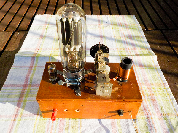
 This is the front view. A speaker is located inside the box.
A bar antenna is located inside too, but an imitation of antenna coil is on the top plate instead.
This is the front view. A speaker is located inside the box.
A bar antenna is located inside too, but an imitation of antenna coil is on the top plate instead.If you put the mouse over the image, it will be
enlarged. (Same below)
 It is the rear view. There are an antenna terminal and a fuse holder.
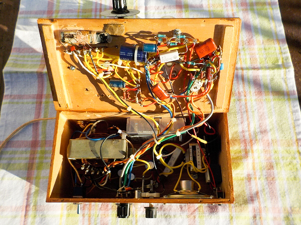
 It is the inside view. The cable connection is disordered due to the small box.
Since the chassis is wooden, there are few worries about an electric shock.
Although I cannot understand the reason, there is no danger even
if it touches on the ground thanks to the double voltage rectification, in case of no transformer.
Moreover, the top plate is just put so that the inside can be seen at any time.
The left big transformer is for the heaters of 6V 2A.
The right is a small output transformer.
It is the inside view. The cable connection is disordered due to the small box.
Since the chassis is wooden, there are few worries about an electric shock.
Although I cannot understand the reason, there is no danger even
if it touches on the ground thanks to the double voltage rectification, in case of no transformer.
Moreover, the top plate is just put so that the inside can be seen at any time.
The left big transformer is for the heaters of 6V 2A.
The right is a small output transformer.
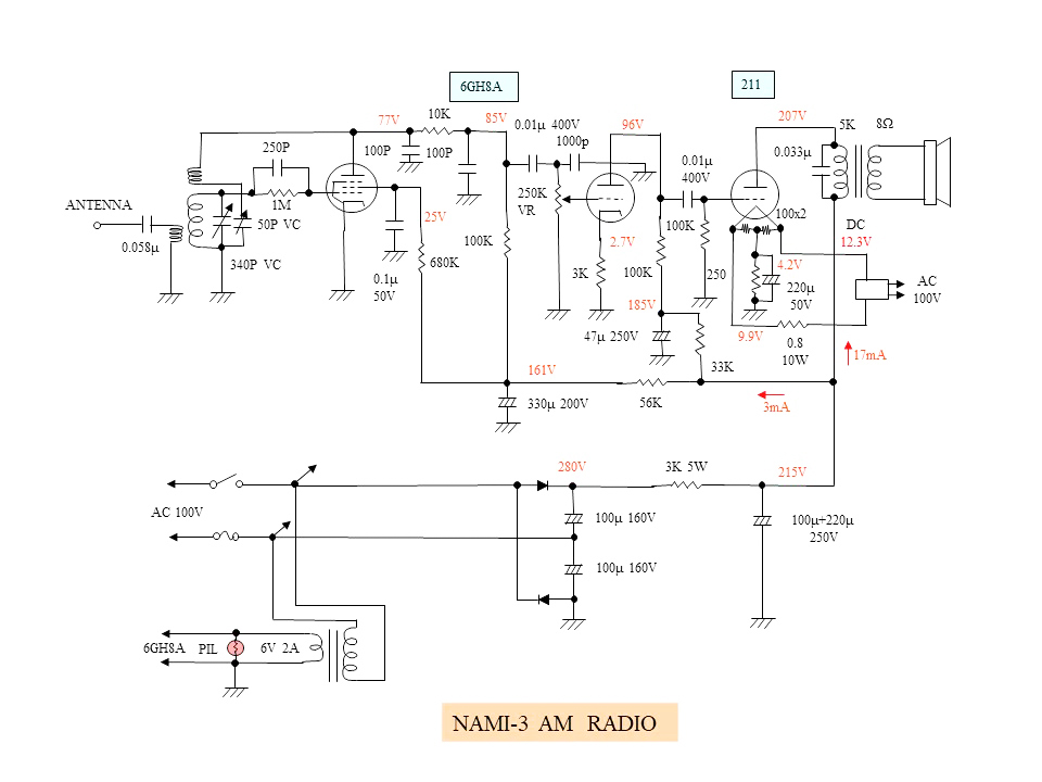 It is the circuit diagram. As the diodes are used instead of a rectifier tube, this can be called as
0-V-2 radio.
It is possible to listen to the radio with an earphone in bedside when I sleep, but only a little
hum noise remains.
It is the circuit diagram. As the diodes are used instead of a rectifier tube, this can be called as
0-V-2 radio.
It is possible to listen to the radio with an earphone in bedside when I sleep, but only a little
hum noise remains.