| Measuring Equipment for Audio |
The vacuum tube amplifier is said to be inferior to the semiconductor amplifier in electrical characteristics. However, when listening to only the sound, the sound of tube amplifier is wonderful as the energy fills the midrange. That's why the vacuum tube amplifier can be made just by the tester only, but I made a millivolt meter and a function generator of AKIZUKI’s MAX038 to measure frequency characteristics. After that, I prepared to be able to measure the distortion ratio using a personal computer. Although there was no problem with the frequency response of the amplifier and the square wave response, I was relieved, but I measured the distortion factor and became astounded at the result and I reviewed the circuit constant of the amplifier sometimes.
 It is a millivolt meter and function generator as seen from the front. The measurement voltage range of
the millivolt meter is 3 mV to 1500 V. Of course, 1500 V is the theoretical value and if such a voltage
is applied, the capacitor will be broken and the IC will be dangerous as well. The photograph measures
the voltage of 1 V of 100 Hz in the 1.5 V range and it agrees with the instruction value of the digital
multimeter. The function generator can continuously vary from 6 Hz to 8.3 MHz. The maximum output voltage
is 4 V p-p (1.4 V rms) for both sine wave and rectangular wave, which is sufficient for measuring the
characteristics of ordinary amplifiers.
It is a millivolt meter and function generator as seen from the front. The measurement voltage range of
the millivolt meter is 3 mV to 1500 V. Of course, 1500 V is the theoretical value and if such a voltage
is applied, the capacitor will be broken and the IC will be dangerous as well. The photograph measures
the voltage of 1 V of 100 Hz in the 1.5 V range and it agrees with the instruction value of the digital
multimeter. The function generator can continuously vary from 6 Hz to 8.3 MHz. The maximum output voltage
is 4 V p-p (1.4 V rms) for both sine wave and rectangular wave, which is sufficient for measuring the
characteristics of ordinary amplifiers.
If you put the mouse over the image, it will be enlarged. (Same below)
 It is inside the millivolt meter. Since it is necessary to accurately adjust the resistance value to
the design value, it is a circulating wiring like a circus because it combines multiple resistors.
Some parts are considerably impossible because all parts are used for scraps. IC is also aerial wiring
on lag board. I admire that I often do not oscillate with this.
It is inside the millivolt meter. Since it is necessary to accurately adjust the resistance value to
the design value, it is a circulating wiring like a circus because it combines multiple resistors.
Some parts are considerably impossible because all parts are used for scraps. IC is also aerial wiring
on lag board. I admire that I often do not oscillate with this.
 It is a circuit diagram of millivoltmeter. The most difficult thing was resistance choice to make
resistance value design value. While measuring with a tester several resistors were connected in
series. Because 1 mA with resistance removed from the hand-held voltmeter of 30 V was used for the
ammeter, the gain of the operational amplifier got larger and 3 mV was the limit, but I thought that
with a 100 μA ammeter it got even more sensitive (less than 1 mV).
It is a circuit diagram of millivoltmeter. The most difficult thing was resistance choice to make
resistance value design value. While measuring with a tester several resistors were connected in
series. Because 1 mA with resistance removed from the hand-held voltmeter of 30 V was used for the
ammeter, the gain of the operational amplifier got larger and 3 mV was the limit, but I thought that
with a 100 μA ammeter it got even more sensitive (less than 1 mV).
 It is the amplitude frequency characteristic of millivoltmeter. It is within + 0 dB / -3 dB from
10 Hz to 100 kHz, so there is no problem with tube amp measurement. However, it seems to be a
little unsatisfactory for semiconductor amps.
It is the amplitude frequency characteristic of millivoltmeter. It is within + 0 dB / -3 dB from
10 Hz to 100 kHz, so there is no problem with tube amp measurement. However, it seems to be a
little unsatisfactory for semiconductor amps.
 It is internal to the function generator. Main is AKIZUKI's MAX038 kit. The power supply of ± 5 V
is purchased at 525 yen for 2 pieces at nearby hard off. Initially I used a 50 kΩ VR on hand to
adjust the output voltage, but when narrowing the VR at frequencies above 100 kHz, the waveform of
the rectangular wave looks like a sine wave. Therefore, when purchasing and exchanging 100 Ω VR,
waveform distortion disappeared. Also, since the output voltage of the original of the MAX038 kit
was as low as 2 V p-p, the negative feedback resistor value of the buffer IC was changed to 4 V p-p.
In the manual of the kit there is a caution notation to directly attach the capacitor that determines
the oscillation frequency to the base, but when it is arranged close to the changeover SW as shown in
the picture, it operates stably without any problem at all. However, since there are only 6 contacts
for switching SW, there are only 6 bands, and frequencies from 0.1 Hz to 6 Hz and from 8.3 MHz to 20
MHz can not be used.
It is internal to the function generator. Main is AKIZUKI's MAX038 kit. The power supply of ± 5 V
is purchased at 525 yen for 2 pieces at nearby hard off. Initially I used a 50 kΩ VR on hand to
adjust the output voltage, but when narrowing the VR at frequencies above 100 kHz, the waveform of
the rectangular wave looks like a sine wave. Therefore, when purchasing and exchanging 100 Ω VR,
waveform distortion disappeared. Also, since the output voltage of the original of the MAX038 kit
was as low as 2 V p-p, the negative feedback resistor value of the buffer IC was changed to 4 V p-p.
In the manual of the kit there is a caution notation to directly attach the capacitor that determines
the oscillation frequency to the base, but when it is arranged close to the changeover SW as shown in
the picture, it operates stably without any problem at all. However, since there are only 6 contacts
for switching SW, there are only 6 bands, and frequencies from 0.1 Hz to 6 Hz and from 8.3 MHz to 20
MHz can not be used.
 This is a circuit diagram of the function generator. As for production precautions, the rectangular
wave is distorted at a high frequency unless the output level adjustment VR is set to be as small as
100 Ω. According to the catalog, the distortion factor of the sinusoidal wave is described as 0.75%,
which is unlikely to be used for measuring the distortion rate (it was 4.4% actually measured). Also,
the sine wave has a habit of having slightly different waveforms in the upper and lower sides. The
frequency band is 6 Hz-100 Hz, 70 Hz-1000 Hz, 600 Hz-9 kHz, 5 kHz-70 kHz, 60 kHz-950 kHz, 500 kHz-8.3
MHz from the lowest.
This is a circuit diagram of the function generator. As for production precautions, the rectangular
wave is distorted at a high frequency unless the output level adjustment VR is set to be as small as
100 Ω. According to the catalog, the distortion factor of the sinusoidal wave is described as 0.75%,
which is unlikely to be used for measuring the distortion rate (it was 4.4% actually measured). Also,
the sine wave has a habit of having slightly different waveforms in the upper and lower sides. The
frequency band is 6 Hz-100 Hz, 70 Hz-1000 Hz, 600 Hz-9 kHz, 5 kHz-70 kHz, 60 kHz-950 kHz, 500 kHz-8.3
MHz from the lowest.
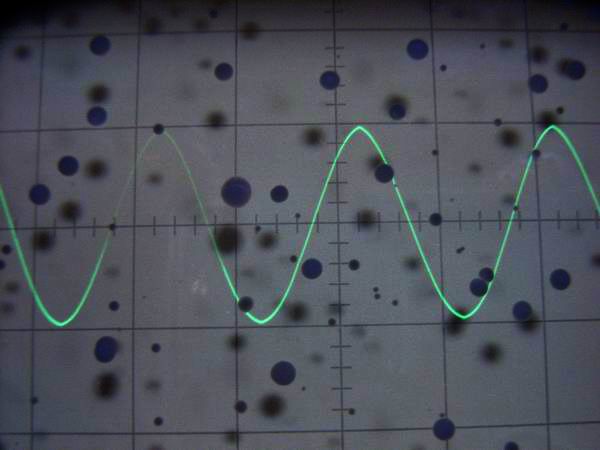
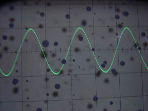
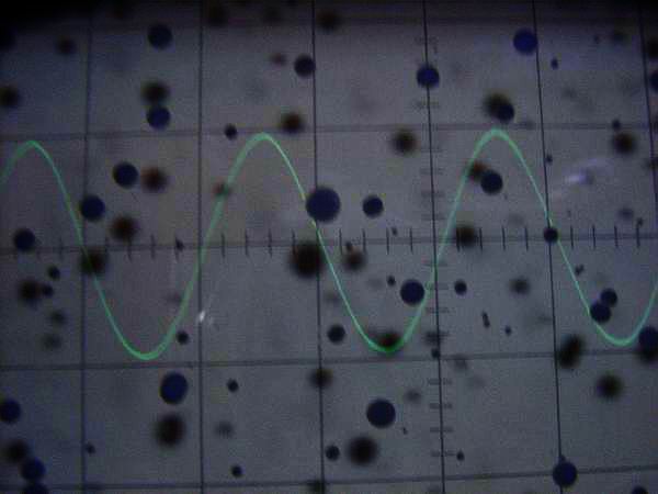
 It is a 2 V p-p sinusoidal waveform of the function generator. From the upper left to the lower right, it
is 100 Hz, 10 kHz, 100 kHz, 1 MHz. The upper and lower waveforms are slightly different and not so beautiful.
This is why the strain rate of 1 kHz is as high as 4.4%. (These pictures can not be enlarged)
It is a 2 V p-p sinusoidal waveform of the function generator. From the upper left to the lower right, it
is 100 Hz, 10 kHz, 100 kHz, 1 MHz. The upper and lower waveforms are slightly different and not so beautiful.
This is why the strain rate of 1 kHz is as high as 4.4%. (These pictures can not be enlarged)
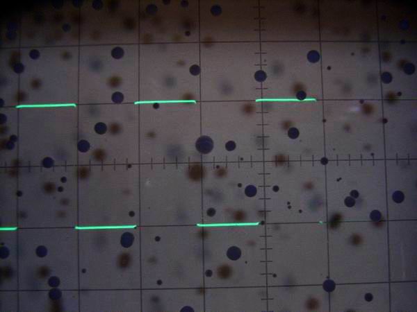
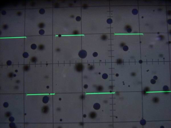
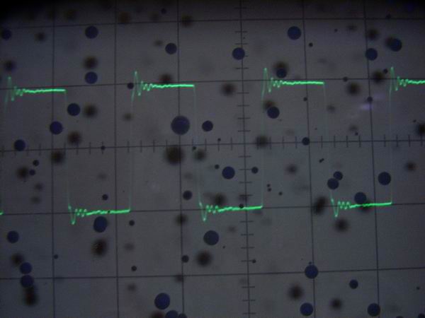
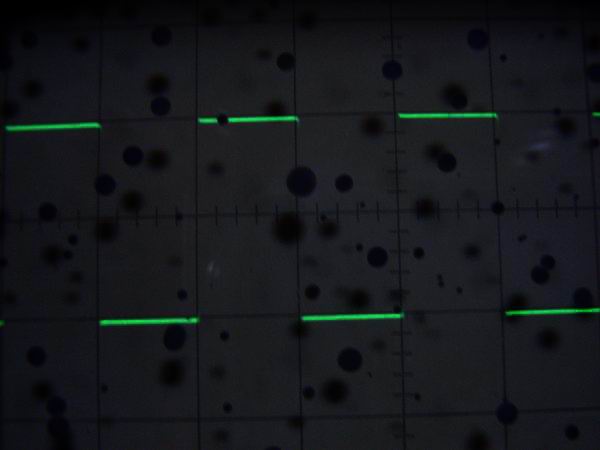 This is a 2 V p-p rectangular waveform of the function generator. From the upper left to the lower right,
it is 100 Hz, 10 kHz, 100 kHz, 1 MHz. Except for 1 MHz ringing, the waveform is relatively clean compared
to the sine wave and it seems to be used for square wave response test. (These pictures can not be enlarged)
This is a 2 V p-p rectangular waveform of the function generator. From the upper left to the lower right,
it is 100 Hz, 10 kHz, 100 kHz, 1 MHz. Except for 1 MHz ringing, the waveform is relatively clean compared
to the sine wave and it seems to be used for square wave response test. (These pictures can not be enlarged)
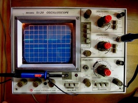 It is an oscilloscope with a 10: 1 probe that can measure up to 20 MHz. I bought it cheaply at the net
auction. Although it is 5520 of KIKUSUI, the signal can be seen up to about 50 MHz by the 5 times
magnification function of the horizontal axis.
It is an oscilloscope with a 10: 1 probe that can measure up to 20 MHz. I bought it cheaply at the net
auction. Although it is 5520 of KIKUSUI, the signal can be seen up to about 50 MHz by the 5 times
magnification function of the horizontal axis.
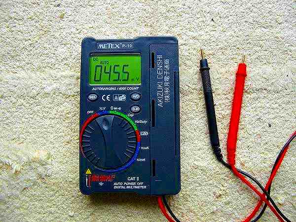 Until very recently I used an analog tester, but as expected the internal resistance can not be ignored
and there are many errors in the measured values so I bought a digital tester. It is about 1,500 yen in
the mail order of AKIZUKI, but it is very convenient to measure the capacity of the capacitor and the
frequency up to 10 MHz.
Until very recently I used an analog tester, but as expected the internal resistance can not be ignored
and there are many errors in the measured values so I bought a digital tester. It is about 1,500 yen in
the mail order of AKIZUKI, but it is very convenient to measure the capacity of the capacitor and the
frequency up to 10 MHz.
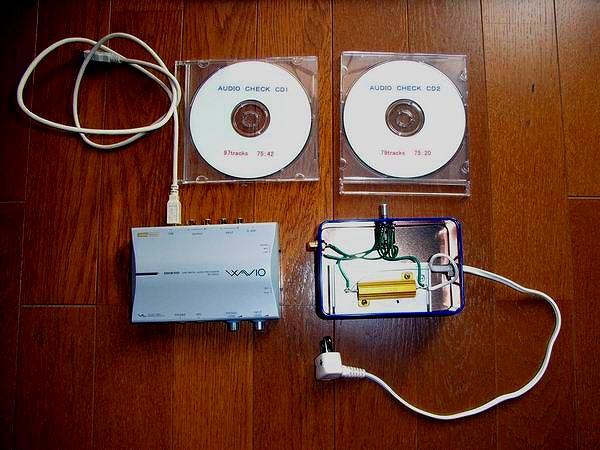 Although the distortion rate measuring device was expensive, we abandoned the measurement, but HP of
SOFTON's Mr. YOSHIMOTO decided to try the audio processor and the method by WaveSpectra. Audio processor
obtained ONKYO's SE-U33GXP cheaply at the net auction. This is useful for internal volume. Although
the problem is low distortion low frequency oscillator, the oscillator possessed is only AKIZUKI MAX038.
However, the distortion is 2%, so it can not be used for distortion measurement very much.
I searched in the net auction and it was sold for 1,000 yen and I bought it immediately. When measured
with WaveSpectra, the distortion factor of the CD reproduction wave is about 0.02% and it seems that
it can be used sufficiently with a tube amp. The problem with the CD regenerative low frequency oscillator
is that the output voltage is as low as 1.5 V at the maximum, and the frequency above 22 kHz does not
come out.
When actually used, there was a problem that the distortion rate sharply increased to several 10% with
output of 3 W to 4 W or more. It seems that the audio processor itself will be distorted when the sound
volume of the SE-U33GXP internal organs is greatly narrowed down. Therefore, when connecting via another
volume for fine adjustment of the input level, it is now possible to measure normally. In the photograph
8 Ω 30 W dummy resistance accommodation box is the volume with SW with 5 kΩ. Turn on SW only when
measuring strain rate.
Although the distortion rate measuring device was expensive, we abandoned the measurement, but HP of
SOFTON's Mr. YOSHIMOTO decided to try the audio processor and the method by WaveSpectra. Audio processor
obtained ONKYO's SE-U33GXP cheaply at the net auction. This is useful for internal volume. Although
the problem is low distortion low frequency oscillator, the oscillator possessed is only AKIZUKI MAX038.
However, the distortion is 2%, so it can not be used for distortion measurement very much.
I searched in the net auction and it was sold for 1,000 yen and I bought it immediately. When measured
with WaveSpectra, the distortion factor of the CD reproduction wave is about 0.02% and it seems that
it can be used sufficiently with a tube amp. The problem with the CD regenerative low frequency oscillator
is that the output voltage is as low as 1.5 V at the maximum, and the frequency above 22 kHz does not
come out.
When actually used, there was a problem that the distortion rate sharply increased to several 10% with
output of 3 W to 4 W or more. It seems that the audio processor itself will be distorted when the sound
volume of the SE-U33GXP internal organs is greatly narrowed down. Therefore, when connecting via another
volume for fine adjustment of the input level, it is now possible to measure normally. In the photograph
8 Ω 30 W dummy resistance accommodation box is the volume with SW with 5 kΩ. Turn on SW only when
measuring strain rate.
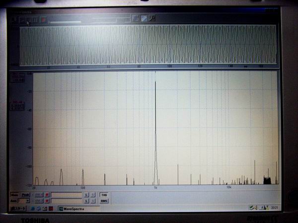
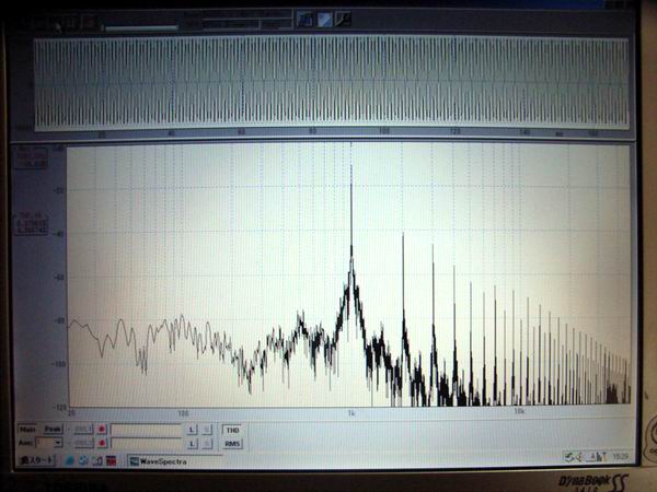 It is an example of a personal computer screen when distortion ratio is measured by audio processor,
WaveSpectra. Here, the distortion factor of the 1 kHz sine wave of the function generator by MAX038
is measured. The load of the generator was measured at 47 kΩ and the output voltage was measured at
2 V p-p (0.71 V rms). On the screen the distortion rate is displayed as 4.36%. There are many harmonics
as seen from the spectrum waveform. By the same measurement, it was 3.45% at 100 Hz and 4.17% at 10 kHz.
It is an example of a personal computer screen when distortion ratio is measured by audio processor,
WaveSpectra. Here, the distortion factor of the 1 kHz sine wave of the function generator by MAX038
is measured. The load of the generator was measured at 47 kΩ and the output voltage was measured at
2 V p-p (0.71 V rms). On the screen the distortion rate is displayed as 4.36%. There are many harmonics
as seen from the spectrum waveform. By the same measurement, it was 3.45% at 100 Hz and 4.17% at 10 kHz.
 CD player, audio processor, WaveSpectra This is an example of a personal computer screen when measuring
distortion ratio. Distortion factor of 1 kHz sine wave is measured. The CD Player load was 47 kΩ and the
output voltage was measured at 2 V p-p (0.71 V rms). In the screen the distortion rate is shown as 0.0265%.
The spectrum waveform is very beautiful compared to the MAX038 oscillator. In the same measurement, it was
0.0275% at 100 Hz and 0.0280% at 10 kHz.
CD player, audio processor, WaveSpectra This is an example of a personal computer screen when measuring
distortion ratio. Distortion factor of 1 kHz sine wave is measured. The CD Player load was 47 kΩ and the
output voltage was measured at 2 V p-p (0.71 V rms). In the screen the distortion rate is shown as 0.0265%.
The spectrum waveform is very beautiful compared to the MAX038 oscillator. In the same measurement, it was
0.0275% at 100 Hz and 0.0280% at 10 kHz.
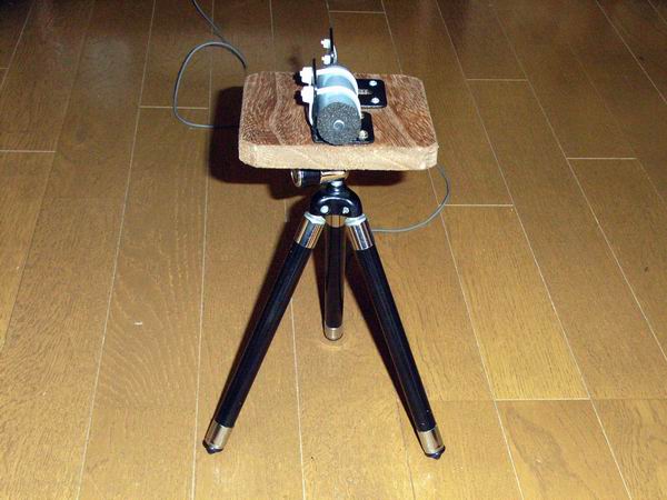 It is a homebrew microphone for measuring the frequency characteristics of the speaker. The two-terminal
electret condenser microphone is taken out from the handy video camera which is no longer used, and it
seems that the frequency characteristic is about 50 Hz to 15 kHz. I fixed it using a tripod head for
handmade camera and a small tripod.
It is a homebrew microphone for measuring the frequency characteristics of the speaker. The two-terminal
electret condenser microphone is taken out from the handy video camera which is no longer used, and it
seems that the frequency characteristic is about 50 Hz to 15 kHz. I fixed it using a tripod head for
handmade camera and a small tripod.