| 6DJ8 Differential Preamplifier |
After coming back to Japan from Paraguay, I did internet surfing to find out something to make, for example, power amplifier or preamplifier, etc. Finally I made a differential preamplifier using RCA 12AU7A.
I enjoyed the sound of its preamplifier for a while but I found some difference in ballance between channels in case of small volume. So I decided to replace the variable resistor with a hand-made resistance attenuator. At the same time I replaced RCA 12AU7A with Matsushita 6DJ8 which is said to excel in the lineality.
 At first I intended to make a preamplifier using FETs but I changed my mind to use the vacuum tubes
which I have got at that time. I bought a deluxe case made by Takachi Corp.
All the transformers are made by Touei Corp., reccomendable for their cheapness.
At first I intended to make a preamplifier using FETs but I changed my mind to use the vacuum tubes
which I have got at that time. I bought a deluxe case made by Takachi Corp.
All the transformers are made by Touei Corp., reccomendable for their cheapness.
If you put the mouse over the image, it will be
enlarged. (Same below)

 This is the inside view of 6DJ8 differential preamplifier. The left is present view and the right past.
It was easy to assemble due to the wide case.
There was no problem for the vacuum tubes without special heat eliminating measures.
Both the input and output have three pairs of RCA jacks. At first it was my trouble that two transformers could
not be fit into the case. Finally I solved this problem after leaning them by 90 degrees and fitting them with
L-type metals.
Since the channel separation in the high frequency band was not good, the input volume was changed into home-made
resistance attenuator, a shield plate was put in the center of the chassis, the wiring of
both channels was separated as much as possible, and the capacity of the electrolytic condenser for
decouplings was increased.
The effect appeared in the following channel separation characteristic.
This is the inside view of 6DJ8 differential preamplifier. The left is present view and the right past.
It was easy to assemble due to the wide case.
There was no problem for the vacuum tubes without special heat eliminating measures.
Both the input and output have three pairs of RCA jacks. At first it was my trouble that two transformers could
not be fit into the case. Finally I solved this problem after leaning them by 90 degrees and fitting them with
L-type metals.
Since the channel separation in the high frequency band was not good, the input volume was changed into home-made
resistance attenuator, a shield plate was put in the center of the chassis, the wiring of
both channels was separated as much as possible, and the capacity of the electrolytic condenser for
decouplings was increased.
The effect appeared in the following channel separation characteristic.
 This is a magnified picture of the hand-made resistance attenuator.
The name of the rotary switch is "32NEG 2-2-23" made by Seiden Corp., and the number of shorting type contact
points is 23. All resistors are 1/2W type with cheaper price.
This attenuator is not a constant impedance type but a simple L-type. After connecting in series the
resistors from zero to 220kohms with the imput resistor of 15kohms, the output is taken out from the
connected point.
This is a magnified picture of the hand-made resistance attenuator.
The name of the rotary switch is "32NEG 2-2-23" made by Seiden Corp., and the number of shorting type contact
points is 23. All resistors are 1/2W type with cheaper price.
This attenuator is not a constant impedance type but a simple L-type. After connecting in series the
resistors from zero to 220kohms with the imput resistor of 15kohms, the output is taken out from the
connected point.
 The picture shows how to install the resistors on the rotary switch made by Seiden.
The copper shield plate is not located in the true center between two contact point plates, so
the resistors with 1/2W type for one channel side are not completely fit into the gap.
A special idea was required to solve it, thus, I installed them at a slant as shown in the picture.
In case of 1/4W type resistors, this problem would not have happened.
The picture shows how to install the resistors on the rotary switch made by Seiden.
The copper shield plate is not located in the true center between two contact point plates, so
the resistors with 1/2W type for one channel side are not completely fit into the gap.
A special idea was required to solve it, thus, I installed them at a slant as shown in the picture.
In case of 1/4W type resistors, this problem would not have happened.
 The curve shows the electrical characteristic of the variable resistor of 50k ohms made by Cosmos
(RV30YG). In the small volume range, there is several dBs of the difference of attenuation between channels.
Also the deterioration of the characteristic is found in both low and high frequency ranges.
I decided to make the resistance attenuator to solve these problems, although it will cost me much.
The curve shows the electrical characteristic of the variable resistor of 50k ohms made by Cosmos
(RV30YG). In the small volume range, there is several dBs of the difference of attenuation between channels.
Also the deterioration of the characteristic is found in both low and high frequency ranges.
I decided to make the resistance attenuator to solve these problems, although it will cost me much.
 This is the electrical characteristic of hand-made resistnace attenuator. A small quantity of unevenness
is found in two curves, but there is no problem when hearing. The resistor of input side is constant as
15k ohms, and the resistors of output side are as follows:
This is the electrical characteristic of hand-made resistnace attenuator. A small quantity of unevenness
is found in two curves, but there is no problem when hearing. The resistor of input side is constant as
15k ohms, and the resistors of output side are as follows:
0 (short), 10, 22, 51, 100, 220, 330, 470, 820, 1k, 1.5k, 2.2k, 3.3k, 4.7k, 6.2k, 8.2k, 10k, 15k,
22k, 33k, 47k, 82k, and 220k ohms. I bought 10 resistors each and selected one after measuring its
resistance by the tester. The curve of resistance percentage is similar to A-type variable resistor.
The quantity of attenuation varies between -63.5 dB and -0.6 dB. The operation of volume control is
smooth without any switching noise due to the adoption of shorting type contact point.
 This is the circuit diagram of 6DJ8 differential preamplifier.
The voltage gain of the preamplifier is only 2.2 times with deep NFB because the gain of my main amplifiers
is high. A switch to change the amount of negative feedback is equipped. I selected two constant current
diodes of 10mA which have the same electrical characteristic from six diodes I bought. There are some reports
that the constant current diodes produce white noises, but any noise did not occur in my case.
This is the circuit diagram of 6DJ8 differential preamplifier.
The voltage gain of the preamplifier is only 2.2 times with deep NFB because the gain of my main amplifiers
is high. A switch to change the amount of negative feedback is equipped. I selected two constant current
diodes of 10mA which have the same electrical characteristic from six diodes I bought. There are some reports
that the constant current diodes produce white noises, but any noise did not occur in my case.
 This is the frequency response of 6DJ8 differential preamplifier.
The effect of bass boosting circuit is outstanding because my speaker system can not produce very low
frequency sound due to its small aperture.
I felt that the sound became softer when using this preamplifier.
This is the frequency response of 6DJ8 differential preamplifier.
The effect of bass boosting circuit is outstanding because my speaker system can not produce very low
frequency sound due to its small aperture.
I felt that the sound became softer when using this preamplifier.
 This is the input vs. output characteristic of 6DJ8 differential preamplifier.
The curve is linear within the output level commonly used, namely from 0.1V to 1.0V.
The voltage gain is 2.2 times, which is sufficient because the gain of my power
amplifiers is high.
This is the input vs. output characteristic of 6DJ8 differential preamplifier.
The curve is linear within the output level commonly used, namely from 0.1V to 1.0V.
The voltage gain is 2.2 times, which is sufficient because the gain of my power
amplifiers is high.
 This is the distortion characteristic of 6DJ8 differential preamplifier. The data for output level over
1.6V can not be obtained because the frequency oscillator is substituted by the CD player.
The distortion rate of the frequency of 100Hz is considerably lower than that of 1kHz and 10kHz.
I think there is no problem because the distortion rate of all the frequency ranges is within 1% for
the common use voltage range of 0.1V to 1.0V. The residual noise is 0.2mV and any noise from the constant
current diodes is not heard.
This is the distortion characteristic of 6DJ8 differential preamplifier. The data for output level over
1.6V can not be obtained because the frequency oscillator is substituted by the CD player.
The distortion rate of the frequency of 100Hz is considerably lower than that of 1kHz and 10kHz.
I think there is no problem because the distortion rate of all the frequency ranges is within 1% for
the common use voltage range of 0.1V to 1.0V. The residual noise is 0.2mV and any noise from the constant
current diodes is not heard.
 This is the channel separation characteristic of 6DJ8 differential preamplifier at the output level of
1V. In the low audio frequency it is excellent but in the high frequency it is deteriorating little
by little. Due to some improvement measures mentioned above, the separation characteristic was improved
in whole frequency band by 10 dB or more. This channel separation curve is very good for the vacuum tube
preamplifier.
This is the channel separation characteristic of 6DJ8 differential preamplifier at the output level of
1V. In the low audio frequency it is excellent but in the high frequency it is deteriorating little
by little. Due to some improvement measures mentioned above, the separation characteristic was improved
in whole frequency band by 10 dB or more. This channel separation curve is very good for the vacuum tube
preamplifier.
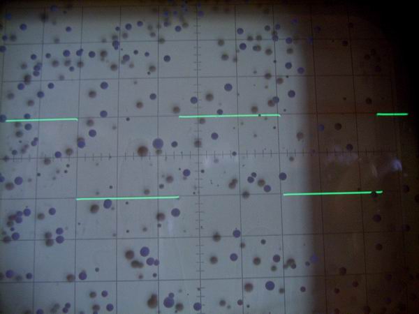
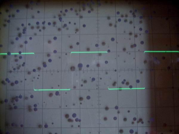
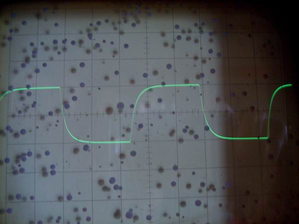
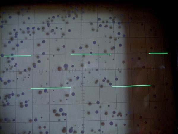 These are the responses of square wave form of 6DJ8 differential preamplifier: from the top, 100Hz,
1kHz, 10kHz, 50kHz and 100kHz. All responses are excellent.
These are the responses of square wave form of 6DJ8 differential preamplifier: from the top, 100Hz,
1kHz, 10kHz, 50kHz and 100kHz. All responses are excellent.