| Headphone Amplifiers |
There is an old ONKYO's small stereo (tuner amplifier: R-811M, CD player: C-722M, speaker: none) bought at the net auction at the bedside and I’m listening with headphone to the Japanese traditional balladic song as lullaby before sleeping. Although there was not much dissatisfaction with the sound, when I checked the circuit of the headphone amplifier, I found that the level was dropped from the main speaker output with the resistor and buffer amplification was carried out with the operational amplifier. "What is this?" So I decided to add a dedicated headphone amplifier behind the volume so that even a little better sound would be obtained. Later, I also made a vacuum tube type headphone amplifier as a vacuum tube lover. I can use it to feel warm when it is cold in winter.
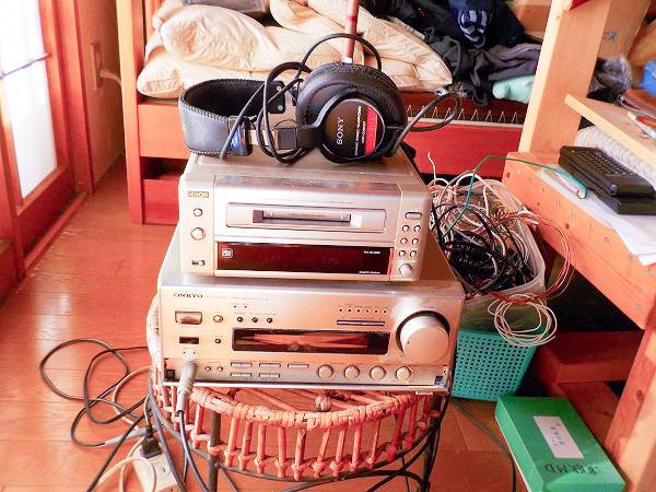 It is my bedside stereo device. While staying in bed, I can reach the CD player, tuner
amplifier, headphone amplifier from the bed. Headphone plays beautiful sounds from bass to treble
with MDR-CD900ST made by SONY. I often fall asleep while listening.
It is my bedside stereo device. While staying in bed, I can reach the CD player, tuner
amplifier, headphone amplifier from the bed. Headphone plays beautiful sounds from bass to treble
with MDR-CD900ST made by SONY. I often fall asleep while listening.
If you put the mouse over the image, it will be enlarged.
(Same below)
 I made a headphone amplifier using two JRC's IC 5532DG removed from SONY's CD player. Amplifier
circuit was
referred to the net information, and after that minor changes were made using resistors and
capacitors on hand. This circuit seems to be able to take twice the output current of one stage
amplification of operational amplifier.
The gain of the amplifier when using 32 Ω headphones is 15 / (22 + 15) x (1 + 10 / 1.5) x 32 /
(33 + 32) = 1.53 times. Since the center terminal of the volume was zero potential, the capacitor
at the amplifier entrance was omitted. As a result of actual measurement, the offset voltage of
the headphone terminal is 2 to 4 mV depending on the volume position, I think that there is no
fear of harming the headphone. The input resistance of 15 kΩ is OK for FET input operational
amplifiers because the bias current is very small, so even 100 kΩ or more is OK, but for bipolar
input operational amplifiers it can not be big enough to suppress the offset voltage. In order
to prevent the input resistance from being connected in parallel to the volume as it is, 22 kΩ
resistor was put in the series. 51 Ω at the output terminal of the operational amplifier is
for preventing oscillation. Although 33 Ω are not required, it is possible to match with the
impedance of the headphone. Negative Feedback Resistor 30 pF in parallel with 10 kΩ is a phase
compensation capacitor that suppresses the peak of the high region. Without this, a peak of + 2.3
dB will be generated around 600 kHz, causing ringing in the square wave response.
I made a headphone amplifier using two JRC's IC 5532DG removed from SONY's CD player. Amplifier
circuit was
referred to the net information, and after that minor changes were made using resistors and
capacitors on hand. This circuit seems to be able to take twice the output current of one stage
amplification of operational amplifier.
The gain of the amplifier when using 32 Ω headphones is 15 / (22 + 15) x (1 + 10 / 1.5) x 32 /
(33 + 32) = 1.53 times. Since the center terminal of the volume was zero potential, the capacitor
at the amplifier entrance was omitted. As a result of actual measurement, the offset voltage of
the headphone terminal is 2 to 4 mV depending on the volume position, I think that there is no
fear of harming the headphone. The input resistance of 15 kΩ is OK for FET input operational
amplifiers because the bias current is very small, so even 100 kΩ or more is OK, but for bipolar
input operational amplifiers it can not be big enough to suppress the offset voltage. In order
to prevent the input resistance from being connected in parallel to the volume as it is, 22 kΩ
resistor was put in the series. 51 Ω at the output terminal of the operational amplifier is
for preventing oscillation. Although 33 Ω are not required, it is possible to match with the
impedance of the headphone. Negative Feedback Resistor 30 pF in parallel with 10 kΩ is a phase
compensation capacitor that suppresses the peak of the high region. Without this, a peak of + 2.3
dB will be generated around 600 kHz, causing ringing in the square wave response.
 It is an easy one just putting op-amp, resistance, and capacitor on a general-purpose board.
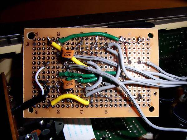 It seems that it works fine without oscillating though it is dirty wiring because parts placement
is not ideal.
It seems that it works fine without oscillating though it is dirty wiring because parts placement
is not ideal.
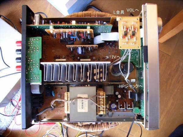 I attached the amplifier board with the L metal fittings to the vacant space of the tuner amplifier.
The power source taken out +12 V and -12 V from the terminals 8 and 4 of the op amp on the back side
of the tuner amplifier board, soldered by disconnecting the wiring to the volume terminal of the
volume with the shielded wire and the output to the headphone terminal. In addition, ± 12 V has a
voltage difference between + 11.6 V and -11.8 V exactly, which seems to be the cause not to make
the output offset 0 mV, but it can not be helped because it can not be adjusted.
I attached the amplifier board with the L metal fittings to the vacant space of the tuner amplifier.
The power source taken out +12 V and -12 V from the terminals 8 and 4 of the op amp on the back side
of the tuner amplifier board, soldered by disconnecting the wiring to the volume terminal of the
volume with the shielded wire and the output to the headphone terminal. In addition, ± 12 V has a
voltage difference between + 11.6 V and -11.8 V exactly, which seems to be the cause not to make
the output offset 0 mV, but it can not be helped because it can not be adjusted.
 It is the amplitude frequency characteristic when 1 V p-p is added to the 33 Ω resistive load. It
is flat from 10 Hz to 150 kHz and is a very broadband characteristic. Although it is the sound of the
key, it seems that distortion became smaller as the number of active elements through which the signal
passes decreases.
It is the amplitude frequency characteristic when 1 V p-p is added to the 33 Ω resistive load. It
is flat from 10 Hz to 150 kHz and is a very broadband characteristic. Although it is the sound of the
key, it seems that distortion became smaller as the number of active elements through which the signal
passes decreases.
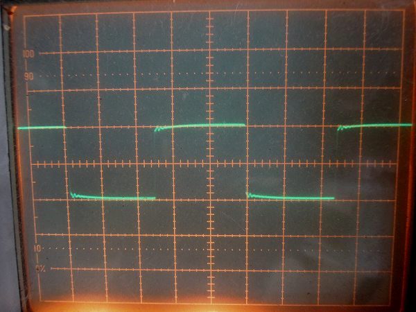
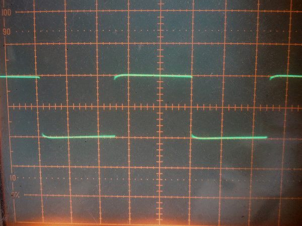
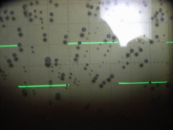 It is a square wave response waveform when 1 V p-p is added to a 33 Ω resistive load. It is a very
beautiful waveform with response waveform of 100 Hz, 1 kHz, 10 kHz, 100 kHz from the top. Even at
100 kHz it keeps the rectangular wave form.
It is a square wave response waveform when 1 V p-p is added to a 33 Ω resistive load. It is a very
beautiful waveform with response waveform of 100 Hz, 1 kHz, 10 kHz, 100 kHz from the top. Even at
100 kHz it keeps the rectangular wave form.
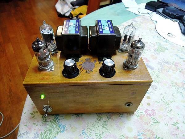 The sound of the op-amp type headphone amplifier is perfect, but as a person who loves vacuum tube,
I want to make a tube type headphone amplifier and made a hand-made all-stage differential push-pull
headphone amplifier with the remnants of the old mini power amplifier.
The sound of the op-amp type headphone amplifier is perfect, but as a person who loves vacuum tube,
I want to make a tube type headphone amplifier and made a hand-made all-stage differential push-pull
headphone amplifier with the remnants of the old mini power amplifier.
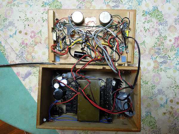 It is inside of vacuum tubular type all-stage differential push-pull headphone amp. Because it
housed many parts in a narrow case, it is embarrassing in the air wiring.
It is inside of vacuum tubular type all-stage differential push-pull headphone amp. Because it
housed many parts in a narrow case, it is embarrassing in the air wiring.
 It is a circuit diagram of a vacuum tube type headphone amplifier. The first stage is 6DJ8 and the
final stage is 12AU7A It is a quite good addition and subtraction constant setting since it used
the assorted parts. The constant current values of 6DJ8 and 12AU7A are 4 mA and 10 mA, respectively,
contributing to low power consumption. In order to reduce residual hum noise, a transistor type
ripple reduction circuit is inserted and hum noise is not heard from the headphones. As a result
of actually measuring the characteristics, the amplification factor of the amplifier was 3 times,
the residual noise was 0.4 mV, and the negative feedback quantity was 3.5 dB.
It is a circuit diagram of a vacuum tube type headphone amplifier. The first stage is 6DJ8 and the
final stage is 12AU7A It is a quite good addition and subtraction constant setting since it used
the assorted parts. The constant current values of 6DJ8 and 12AU7A are 4 mA and 10 mA, respectively,
contributing to low power consumption. In order to reduce residual hum noise, a transistor type
ripple reduction circuit is inserted and hum noise is not heard from the headphones. As a result
of actually measuring the characteristics, the amplification factor of the amplifier was 3 times,
the residual noise was 0.4 mV, and the negative feedback quantity was 3.5 dB.
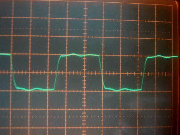
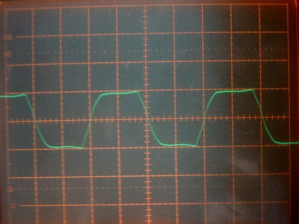
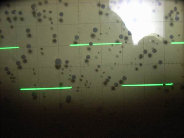
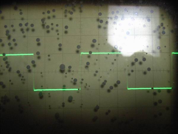
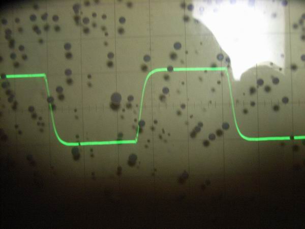
 It is square wave response waveform when 1 V p-p is added to 33 Ω resistive load. From the top,
it is a response waveform of 100 Hz, 1 kHz, 10 kHz, 50 kHz. I think that it is the characteristic
of the output transformer, ringing can be seen at a high frequency, but there is no problem on
hearing at all.
It is square wave response waveform when 1 V p-p is added to 33 Ω resistive load. From the top,
it is a response waveform of 100 Hz, 1 kHz, 10 kHz, 50 kHz. I think that it is the characteristic
of the output transformer, ringing can be seen at a high frequency, but there is no problem on
hearing at all.