| FET Differential Preamplifier |
Although the sound of 6DJ8 differential preamplifier was wonderful as expected, when the volume of main amplifier is the maximum, there is a problem that some noise is conspicuous at the time of semiconductor main amplifier connection. At the time of preamplifier use, unless the volume of the main amplifier is the maximum, my heart does not settle down somehow. Then, I decided to modify it to an FET differential preamplifier aiming at "mild preamplifier."
Basic concept for modification:
1. Since I have no money to make new preamplifier, I decided to modify it using the existing parts as much as possible.
2. Although the improvement of other electrical specifications is also aimed at, noise reduction is set as the maximum target.
3. Since their characteristics differ, two or more FETs are purchased and the best selection is carried out.
4. Without using the constant current diode, FETs are used from a viewpoint of noise reduction.
 2SK30A GR rank is used as the constant current element.
Since two pieces of which characteristic is equal are required, I purchased 10 pieces.
It was less than 4 dollars, which is extraordinary low price.
The graph shows the deviation of Idss in the state where DC 5V is added.
Among them, I decided to use two pieces, namely 4.08 mA and 4.1 mA.
2SK30A GR rank is used as the constant current element.
Since two pieces of which characteristic is equal are required, I purchased 10 pieces.
It was less than 4 dollars, which is extraordinary low price.
The graph shows the deviation of Idss in the state where DC 5V is added.
Among them, I decided to use two pieces, namely 4.08 mA and 4.1 mA.
If you put the mouse on the image, it will be
enlarged. (Same below)
 Since four pieces of 2SK170 are required in total, I purchased 20.
The price was less than 10 dollars for 20 pieces.
Since it is BL rank, Idss is distributed between 6 and 12 mA.
In order to make the gain equal as much as possible, I decided to use four FETs of which Idss
is nearly 7.5 mA from the measurement result.
The final selection is to measure the potential difference between drains in the actual
amplification circuit, and to sort out combination with the smallest potential difference.
Finally 7.45 mA piece was used for the right channel and 7.63 mA for left.
Since four pieces of 2SK170 are required in total, I purchased 20.
The price was less than 10 dollars for 20 pieces.
Since it is BL rank, Idss is distributed between 6 and 12 mA.
In order to make the gain equal as much as possible, I decided to use four FETs of which Idss
is nearly 7.5 mA from the measurement result.
The final selection is to measure the potential difference between drains in the actual
amplification circuit, and to sort out combination with the smallest potential difference.
Finally 7.45 mA piece was used for the right channel and 7.63 mA for left.
 This is the inside view of FET differential preamplifier.
The parts of the vacuum tube differential preamplifier are used almost as they are.
The different points are; twisted 2 cores shield line around AC line aimed at hum noise reduction,
copper plate for the electrostatic shield on the heater transformer, copper plate shield
extension within the chassis aiming at cross talk reduction between right-and-left channels
and power supply part, etc.
This is the inside view of FET differential preamplifier.
The parts of the vacuum tube differential preamplifier are used almost as they are.
The different points are; twisted 2 cores shield line around AC line aimed at hum noise reduction,
copper plate for the electrostatic shield on the heater transformer, copper plate shield
extension within the chassis aiming at cross talk reduction between right-and-left channels
and power supply part, etc.
 This is the inside view of FET differential preamplifier photoed from another angle.
 This is the circuit diagram of FET differential preamplifier.
Double voltage rectification of the heater transformer of 12V is applied to get DC 35V,
and stable 24V is obtained by 3-terminal regulator.
DC 35V is divided into +20V and -4V by use of resistance and LED.
Although 110V and 220V winding of the transformer for B power
supply connected in series is re-used as a choke coil, the degree of its effect is unknown.
This is the circuit diagram of FET differential preamplifier.
Double voltage rectification of the heater transformer of 12V is applied to get DC 35V,
and stable 24V is obtained by 3-terminal regulator.
DC 35V is divided into +20V and -4V by use of resistance and LED.
Although 110V and 220V winding of the transformer for B power
supply connected in series is re-used as a choke coil, the degree of its effect is unknown.
 The graph shows the correlativity of Idss deviation and the drain potential difference of the
right channel, and Idss deviation and drain potential difference are mostly in direct proportion.
Standard Idss is 7.45 mA. Judging from the graph, it is to say that the deviation of Idss has to be
less than 0.25 mA in order to keep the drain potential difference within 0.5V (equivalent to 5% of
the drain voltage).
As a result of measurement, the FET with Idss 7.81 mA of which drain potential difference is 45 mV
is selected.
The graph shows the correlativity of Idss deviation and the drain potential difference of the
right channel, and Idss deviation and drain potential difference are mostly in direct proportion.
Standard Idss is 7.45 mA. Judging from the graph, it is to say that the deviation of Idss has to be
less than 0.25 mA in order to keep the drain potential difference within 0.5V (equivalent to 5% of
the drain voltage).
As a result of measurement, the FET with Idss 7.81 mA of which drain potential difference is 45 mV
is selected.
 This is the potential difference measurement result of the left channel.
Standard Idss is 7.63 mA and it is also to say that the deviation of Idss has to be
less than 0.25 mA in order to keep the drain potential difference within 0.5V (equivalent to 5% of
the drain voltage).
As a result of measurement the FET with Idss 7.66 mA of which drain potential difference is 265 mV
is selected.
This is the potential difference measurement result of the left channel.
Standard Idss is 7.63 mA and it is also to say that the deviation of Idss has to be
less than 0.25 mA in order to keep the drain potential difference within 0.5V (equivalent to 5% of
the drain voltage).
As a result of measurement the FET with Idss 7.66 mA of which drain potential difference is 265 mV
is selected.
 This is the amplitude frequency characteristic of FET differential preamplifier.
It is excellent in low frequency area, but it is to say that attenuation in the high
frequency is not so good for semiconductor amplifier.
But it is success in the high frequency characteristic of this level as "mild preamplifier."
The bass boost function is well effective.
This is the amplitude frequency characteristic of FET differential preamplifier.
It is excellent in low frequency area, but it is to say that attenuation in the high
frequency is not so good for semiconductor amplifier.
But it is success in the high frequency characteristic of this level as "mild preamplifier."
The bass boost function is well effective.
 This is the input-and-output characteristic of FET differential preamplifier.
In the output voltage range (0.1-1V) used regularly, I think it is linear enough.
Although the voltage gain is only 2.7 times, since the gain of my power amplifier is large, it is
enough.
This is the input-and-output characteristic of FET differential preamplifier.
In the output voltage range (0.1-1V) used regularly, I think it is linear enough.
Although the voltage gain is only 2.7 times, since the gain of my power amplifier is large, it is
enough.
 This is the distortion characteristic of FET differential preamplifier.
Since the oscillator is CD regenerative system, there is no data of the output beyond 2V.
Moreover, actual ability may be better than these data, since the residual distortion rate of
my distortion meter is about 0.02%.
Since it is about 0.1% or less on all the frequency in the common voltage range (0.1-1V), it is
satisfactory.
As for the residual noise, it is difficult to measure exactly, because my hand-made mV-meter has
only 3 mV range. If it reads forcibly, it will be about 0.01 to 0.02 mV.
This is the distortion characteristic of FET differential preamplifier.
Since the oscillator is CD regenerative system, there is no data of the output beyond 2V.
Moreover, actual ability may be better than these data, since the residual distortion rate of
my distortion meter is about 0.02%.
Since it is about 0.1% or less on all the frequency in the common voltage range (0.1-1V), it is
satisfactory.
As for the residual noise, it is difficult to measure exactly, because my hand-made mV-meter has
only 3 mV range. If it reads forcibly, it will be about 0.01 to 0.02 mV.
 This is the cross talk characteristic of FET differential preamplifier at 1V output level.
Since it measured by WaveSpectra, there are data only from 20 Hz to 20 kHz.
It is improved as about 10 dB compared with 6DJ8 differential preamplifier.
Is it the result of the extended shield panel in the chassis or the mass
electrolytic condenser for the power supply?
This is the cross talk characteristic of FET differential preamplifier at 1V output level.
Since it measured by WaveSpectra, there are data only from 20 Hz to 20 kHz.
It is improved as about 10 dB compared with 6DJ8 differential preamplifier.
Is it the result of the extended shield panel in the chassis or the mass
electrolytic condenser for the power supply?
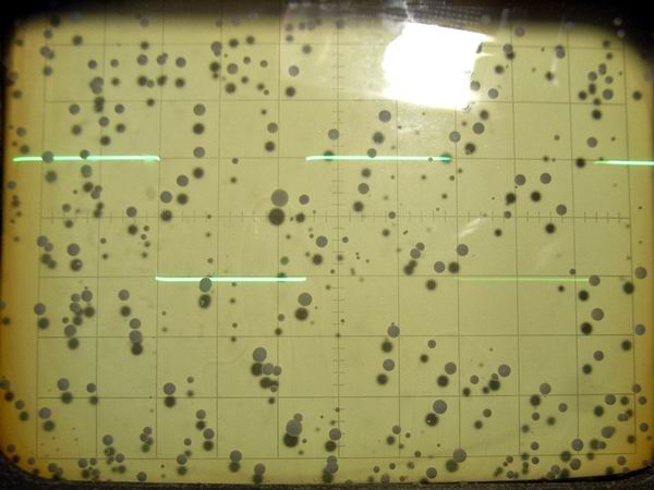
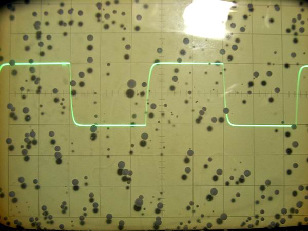
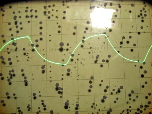
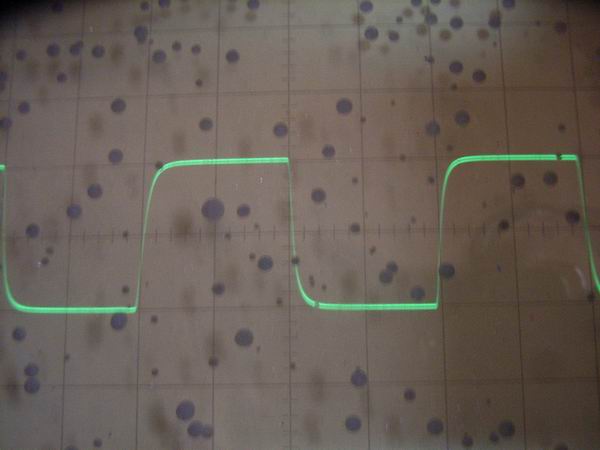
 These are the rectangular wave response waveforms at the condition of 2 Vp-p of FET differential
preamplifier.
From the top, 20 Hz, 100 Hz, 1 kHz, 10 kHz, 50 kHz and 100kHz. Compared with the
excellent characteristic in the low frequency, it is a little bit poor in the high frequency.
These are the rectangular wave response waveforms at the condition of 2 Vp-p of FET differential
preamplifier.
From the top, 20 Hz, 100 Hz, 1 kHz, 10 kHz, 50 kHz and 100kHz. Compared with the
excellent characteristic in the low frequency, it is a little bit poor in the high frequency.


Comments after the Modification from Vacuum Tube to FET:
1. Noise, especially hum noise decreased.
2. The sound became mild probably because the distortion rate decreased.
3. Probably because the cross-talk between channels decreased, a feeling of depth of
sound increased.
4. No noise can be heard even if it strikes the case.
Report on Exchange of FET from 2SK170 to 2SK117:
I was concerned that the high frequency characteristic of this preamplifier was not so good, so
I changed the FET to 2SK117 and measured the square wave characteristics etc. The input capacitance
of 2SK170 is 30pF and the feedback capacitance is 6pF, whereas 2SK117 is about half of 13pF and
3pF respectively, so I thought that the high frequency characteristics could be improved. I measured
Idss with DC 9 V of 10 pieces of 2SK117BL I newly purchased, and selected 2 pairs, that is,
10.88 mA / 10.92 mA and 11.04 mA / 11.17 mA. After the exchange, the gain of the preamplifier slightly
lowered with the decrease of gm, but some improvement of high frequency characteristic was seen. As a
result of FET exchange, it seems that the sound of high region has become clearer.
 It is amplitude frequency characteristic of 2SK117 differential preamplifier. It is understood
that the characteristics are improved in the high region compared with 2SK170. Is it an effect
that input and feedback capacitance became half ?
It is amplitude frequency characteristic of 2SK117 differential preamplifier. It is understood
that the characteristics are improved in the high region compared with 2SK170. Is it an effect
that input and feedback capacitance became half ?
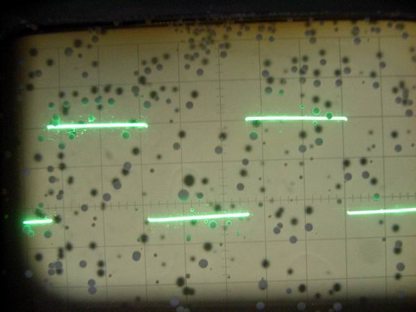
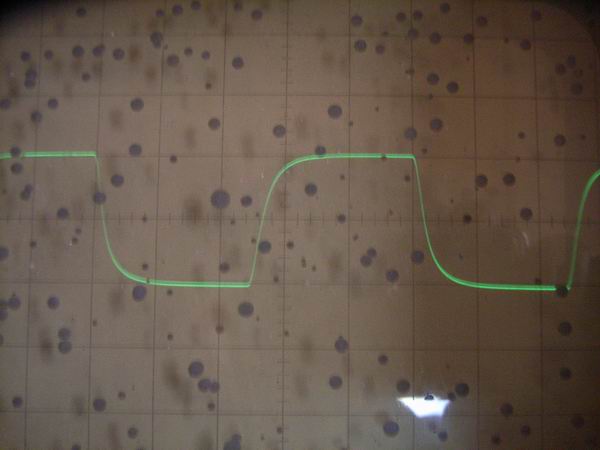
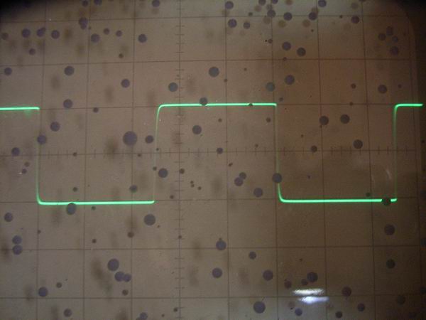 These are square wave response waveform at 2 V p-p of 2SK117 differential preamplifier, from
the top, 10 kHz, 50 kHz, and 100 kHz. The rising characteristic is improved compared to 2SK170.
These are square wave response waveform at 2 V p-p of 2SK117 differential preamplifier, from
the top, 10 kHz, 50 kHz, and 100 kHz. The rising characteristic is improved compared to 2SK170.
Final Improvement Report:
 Finally I took place some improvement in this preamplifier, that is, enhancement of power supply
unit, elimination of pop noise at the time of power injection, enhansment of bass boost circuit,
and installation of bypass circuit. The final circuit diagram is shown in the picture.
Finally I took place some improvement in this preamplifier, that is, enhancement of power supply
unit, elimination of pop noise at the time of power injection, enhansment of bass boost circuit,
and installation of bypass circuit. The final circuit diagram is shown in the picture.