| Improvement of Master Clock of CD Player |
I replaced a master clock of SONY's CD Player CDP-X55ES, which I cheaply got from the internet auction, with a high stabilized oscillator. Lots of people report in their web site that they got a good result after changing the clock to high stabilized oscillator. Thus I decided to challenge modifying CDP-X55ES. I bought the high stabilized crystal oscillator from Pract Sound System by a mail order. It is said that the frequency stability of the clock oscillator for normal CD players is several ten ppm. The 45.1584 MHz oscillator which I bought this time is proud of high stability of 2.5 ppm.
 SONY's CDP-X55ES is seen on the upper part of the picture.
It is a product put on sale in 1989 and is amazed at the amount of resources for the peak time of bubble.
Though it is a normal CD player, its weight is 12.5kg and the side wood is luxurious.
Main specifications are as follows:
SONY's CDP-X55ES is seen on the upper part of the picture.
It is a product put on sale in 1989 and is amazed at the amount of resources for the peak time of bubble.
Though it is a normal CD player, its weight is 12.5kg and the side wood is luxurious.
Main specifications are as follows:Frequency response: 2Hz to 20kHz ±0.3dB
Signal to noise ratio: 115dB
Dynamic range: 100dB
Channel separation: 110dB
Weight: 12.5kg
When you put the mouse on the image, it will be
magnified.
 This is the view when the top cover is detached.
I forgot to take a photograph before detaching the parts such as crystal oscillator, resistor etc.
There are two big exclusive transformars for analog and digital usages.
There are two sets of crystal oscillators for master clock and motor drive.
The frequency of the master clock is 45.1584 MHz, but the one for motor drive is unclear in detail.
This is the view when the top cover is detached.
I forgot to take a photograph before detaching the parts such as crystal oscillator, resistor etc.
There are two big exclusive transformars for analog and digital usages.
There are two sets of crystal oscillators for master clock and motor drive.
The frequency of the master clock is 45.1584 MHz, but the one for motor drive is unclear in detail.
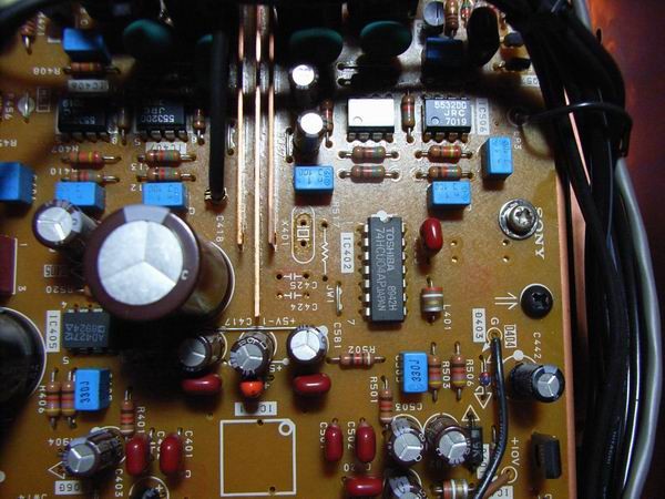
 This is the picture of master clock circuit to be improved this time.
I can see a crystal of 45.1584MHz, a resistor of 10 kΩ, two condensers of 10 pF,
a high speed MOS inverter IC of 74HCU04 for the oscillation and buffer amplification.
This is the picture of master clock circuit to be improved this time.
I can see a crystal of 45.1584MHz, a resistor of 10 kΩ, two condensers of 10 pF,
a high speed MOS inverter IC of 74HCU04 for the oscillation and buffer amplification.
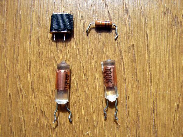 These are the parts detached from the base. I keep them for unexpected accident during the
improvement. The crystal is covered with an electromagnetic shield tape.
These are the parts detached from the base. I keep them for unexpected accident during the
improvement. The crystal is covered with an electromagnetic shield tape.
 This is the picture after detaching four parts mentioned above.
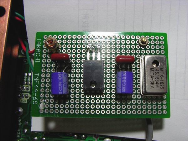 This is the picture after attaching high precision crystal oscillator of 45.1584 MHz on a small
universal base. High frequency choke coil is inserted to protect the leak of clock signal to
the DC supply of +12V.
This is the picture after attaching high precision crystal oscillator of 45.1584 MHz on a small
universal base. High frequency choke coil is inserted to protect the leak of clock signal to
the DC supply of +12V.
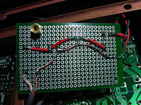 This is the opposite side of universal base.
 The universal base is installed at the opposite side of main base of CD player using two spacers of 10mm long.
The DC supply of +12V is connected with a pair of copper wires, the supply of clock with a coaxial cable
of 50 Ω.
The universal base is installed at the opposite side of main base of CD player using two spacers of 10mm long.
The DC supply of +12V is connected with a pair of copper wires, the supply of clock with a coaxial cable
of 50 Ω.
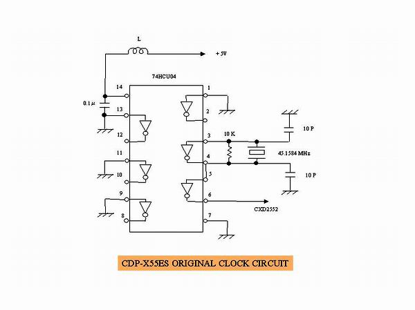 This is the original circuit diagram for the oscillation and buffer amplification of master clock.
A high speed MOS inverter IC, 74HCU04 is used. Only 2 inverters out of 6 are used, earthing 4 vacant inverters.
One inverter is used for oscillation and the other for buffer amplification.
The power supply is connected to +5V through an LC low pass filter.
This is the original circuit diagram for the oscillation and buffer amplification of master clock.
A high speed MOS inverter IC, 74HCU04 is used. Only 2 inverters out of 6 are used, earthing 4 vacant inverters.
One inverter is used for oscillation and the other for buffer amplification.
The power supply is connected to +5V through an LC low pass filter.
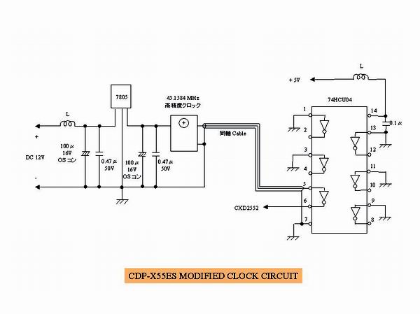 This is the circuit diagram of improved master clock supplier. An exclusive 3-terminal voltage regulator of
+5V is attached for the new master clock oscillator.
At the input of the +5V regulator, a choke coil, an OS condenser of 100μF and a film condenser of 0.47μF
are equipped. At the output side, an OS condenser of 100μF and a film condenser of 0.47μF are installed.
This is the circuit diagram of improved master clock supplier. An exclusive 3-terminal voltage regulator of
+5V is attached for the new master clock oscillator.
At the input of the +5V regulator, a choke coil, an OS condenser of 100μF and a film condenser of 0.47μF
are equipped. At the output side, an OS condenser of 100μF and a film condenser of 0.47μF are installed.
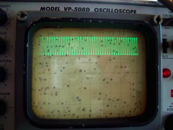 This is the wave form of improved master clock at the output of buffer amplifier of 74HCU04 on the screen
of oscilloscope. It is read as the frequency of 45 MHz and the voltage level of +2.5V ±1V.
This is the wave form of improved master clock at the output of buffer amplifier of 74HCU04 on the screen
of oscilloscope. It is read as the frequency of 45 MHz and the voltage level of +2.5V ±1V.
Impression on the sound after improvement:
I report my impression only on the sound, because it is difficult to measure the electrical characteristic
of CD player with measuring instruments of an amateur.
In short, the sound resolution considerably became high.
The high frequency sound became very beautiful.
I've got another benefit.
Out of many CDs of mine, there was a jazz piano CD with the skip of sound, which I bought
at the recycle shop.
The sound skip, however, completely disappeared by the improvement of master clock. I think I got a big
crop by a small investment.