| Modification of CB Machine to 7MHz AM |
I previously modified an old CB machine of 40 CH to operate it on 28 MHz AM. but I couldn't find operating station easily, although it is said in the internet that 28.305 MHz is pretty active. Will it be useless unless sporadic E zone appears during the spring and the summer ? So I got another junk CB machine and decided to remodel it to AM machine of 7 MHz. As a result of preliminary examination, remodeling to 28 MHz is relatively easy, but remodeling to 7 MHz seemed to be quite difficult. Therefore, I aimed at CB machine of a crystal synthesizer type which seems to be as simple as possible. Even if it searches on the net, there is 50 MHz remodeling example from the CB machine, but there is no 7 MHz remodeling example, and since there is no circuit diagram of the CB machine which I got, it became very hard remodeling. Finally I managed to be able to send and receive 7MHz AM wave at a cost of about 3,000 yen.
 It is the CB machine, New Colt 450, which I got inexpensively. It is illegal multichannel and
high output machine even in the US FCC. It is quipped with main dial of 23 channels (totally 46CH
by High and Low switching), power switch with volume, squelch volume, transmit power adjustment
volume, CB/PA switching, noise blanker switching, and long/near distance reception sensitivity
switch. There seems to be no problem in reception, and at 27.005 MHz (CH 4), I hear the bustling
voice of illegal operation tracker. The transmission has a carrier output of about 7 W, and as I
whistle, the needle of the wattmeter can swing up to about 20 W so it is expected to have deep
and sharp modulation sound. Although the appearance is very rusty, the interior is comparatively
beautiful and electrical performance seems to be no problem. The rusty case is planned to paint
after the inside remodeling is over.
It is the CB machine, New Colt 450, which I got inexpensively. It is illegal multichannel and
high output machine even in the US FCC. It is quipped with main dial of 23 channels (totally 46CH
by High and Low switching), power switch with volume, squelch volume, transmit power adjustment
volume, CB/PA switching, noise blanker switching, and long/near distance reception sensitivity
switch. There seems to be no problem in reception, and at 27.005 MHz (CH 4), I hear the bustling
voice of illegal operation tracker. The transmission has a carrier output of about 7 W, and as I
whistle, the needle of the wattmeter can swing up to about 20 W so it is expected to have deep
and sharp modulation sound. Although the appearance is very rusty, the interior is comparatively
beautiful and electrical performance seems to be no problem. The rusty case is planned to paint
after the inside remodeling is over.
If you put the mouse over the image, it will be enlarged. (Same below)
 It is the inside view. The last stage transistor is 2SC1969, the driver is 2SC1567, and the
modulator is 2SD553 push-pull, which seems to be the device commonly used for CB radio. The
modulation transformer is large and it can be expected that deep modulation will take place.
From my experiences I feel that the push-pull transistor system will be more strongly modulated
than the boosting of the AM modulator by adding the low impedance output of IC power amplifier
to the 8 Ω terminal of the modulation transformer.
It is the inside view. The last stage transistor is 2SC1969, the driver is 2SC1567, and the
modulator is 2SD553 push-pull, which seems to be the device commonly used for CB radio. The
modulation transformer is large and it can be expected that deep modulation will take place.
From my experiences I feel that the push-pull transistor system will be more strongly modulated
than the boosting of the AM modulator by adding the low impedance output of IC power amplifier
to the 8 Ω terminal of the modulation transformer.
 Before remodeling it is necessary to understand the block diagram of the CB radio. I found the
transmission system diagram on the net, but finally I can’t find the detailed circuit diagram
at all. In other words, it was fumbled to remodel it while referring to NASA's transmission/reception
system diagram and circuit diagram. This machine is the quartz synthesizer system with 12 main
crystals and 8 sub-crystals, and it can be combined up to 48 CH, but it is 46 CH machine from
the main dial contact number. The noise blanker, the squelch, and the AGC function are complicated
circuits, so it is difficult to go through the circuit, so I decided not to touch it. Receiving is
a double super heterodyne (first IF = 10 MHz band, second IF = 455 kHz), transmission is single
conversion method. Receive selectivity is determined by CFU455H and the -6 dB bandwidth is 6 kHz.
This filter is planned to be replaced as the skirt characteristics are not so good.
Before remodeling it is necessary to understand the block diagram of the CB radio. I found the
transmission system diagram on the net, but finally I can’t find the detailed circuit diagram
at all. In other words, it was fumbled to remodel it while referring to NASA's transmission/reception
system diagram and circuit diagram. This machine is the quartz synthesizer system with 12 main
crystals and 8 sub-crystals, and it can be combined up to 48 CH, but it is 46 CH machine from
the main dial contact number. The noise blanker, the squelch, and the AGC function are complicated
circuits, so it is difficult to go through the circuit, so I decided not to touch it. Receiving is
a double super heterodyne (first IF = 10 MHz band, second IF = 455 kHz), transmission is single
conversion method. Receive selectivity is determined by CFU455H and the -6 dB bandwidth is 6 kHz.
This filter is planned to be replaced as the skirt characteristics are not so good.
 I successfully selected the main crystal from the transmission system diagram and investigated
whether it can be remodeled to 7 MHz. As a result, I found that if 17.79 MHz crystal is
available, 4 waves of 7.195, 7.175, 7.165, 7.155 MHz can be transmitted and received. Naturally,
all 27 MHz tuning coils need to be replaced for 7 MHz. However, since such an omission crystal
is not in the market, it will be custom made. Special order of crystal is high cost (3-4 thousand
yen?), And 4 waves with 10 kHz or 20 kHz are not so meaningful. Therefore, I aimed at simplification
by narrowing down to one wave of 7.195 MHz for the time being. Crystal is easy and cheap because I
can buy two with 800 yen for Sato Electric. AM mode at 7 MHz is operated at 7.195 MHz with a
probability of nearly 100%, I will decide the wave propagation after looking at 7.181 MHz which
is supposed to be the reserved frequency. Reception can be simplified using an IC such as LA1600,
but I decided to use the original circuit as much as possible. The reception after remodeling is a
single super method (IF = 455 kHz), and the transmission is direct crystal oscillation without
conversion.
I successfully selected the main crystal from the transmission system diagram and investigated
whether it can be remodeled to 7 MHz. As a result, I found that if 17.79 MHz crystal is
available, 4 waves of 7.195, 7.175, 7.165, 7.155 MHz can be transmitted and received. Naturally,
all 27 MHz tuning coils need to be replaced for 7 MHz. However, since such an omission crystal
is not in the market, it will be custom made. Special order of crystal is high cost (3-4 thousand
yen?), And 4 waves with 10 kHz or 20 kHz are not so meaningful. Therefore, I aimed at simplification
by narrowing down to one wave of 7.195 MHz for the time being. Crystal is easy and cheap because I
can buy two with 800 yen for Sato Electric. AM mode at 7 MHz is operated at 7.195 MHz with a
probability of nearly 100%, I will decide the wave propagation after looking at 7.181 MHz which
is supposed to be the reserved frequency. Reception can be simplified using an IC such as LA1600,
but I decided to use the original circuit as much as possible. The reception after remodeling is a
single super method (IF = 455 kHz), and the transmission is direct crystal oscillation without
conversion.
 I don’t know exactly how to remodel it only by new block diagram, so I will explain a bit. However,
please be careful as there may be mistakes about the detailed numerical value of the element. First
of all, although it is a transmission system, I skipped the 37 MHz and 10 MHz band mixer (2SC839),
connected the oscillation signal of 7.195 MHz to the base of RF AMP (2SC2003), and exchanged the
collector tuning coil for 7 MHz. Likewise, 4 coils for 27 MHz were removed and replaced with 4: 1
and 1: 5.5 transmission transformers and 2-stage pi type LPF. Many CB radios adopt a narrow band
tuning circuit for impedance matching of the final stage transistor, but since it is difficult to
procure and adjust the parts at 7 MHz, I adopt the transmission transformer type wide band circuit
by Toroidal core. Initially, the output side of the final stage was also changed to 1: 4 bifilar
winding. Since the output was only 4 W, I changed it to 1: 5.5 (exactly ((1+ (16/12)) ^ 2 = 5.44).
I don’t know exactly how to remodel it only by new block diagram, so I will explain a bit. However,
please be careful as there may be mistakes about the detailed numerical value of the element. First
of all, although it is a transmission system, I skipped the 37 MHz and 10 MHz band mixer (2SC839),
connected the oscillation signal of 7.195 MHz to the base of RF AMP (2SC2003), and exchanged the
collector tuning coil for 7 MHz. Likewise, 4 coils for 27 MHz were removed and replaced with 4: 1
and 1: 5.5 transmission transformers and 2-stage pi type LPF. Many CB radios adopt a narrow band
tuning circuit for impedance matching of the final stage transistor, but since it is difficult to
procure and adjust the parts at 7 MHz, I adopt the transmission transformer type wide band circuit
by Toroidal core. Initially, the output side of the final stage was also changed to 1: 4 bifilar
winding. Since the output was only 4 W, I changed it to 1: 5.5 (exactly ((1+ (16/12)) ^ 2 = 5.44).
 The receiving system skipped the 27 MHz band → 10 MHz band mixer (2SC839) and pushed the
output of the 7 MHz receiving amplifier to the base of the 10 MHz band → 455 kHz band mixer
(2SC839). Of course, the tuning coil of the receiving amplifier was also changed from 27 MHz to
7 MHz. Originally, I could not hear the received noise at all, but I was able to hear 7.195 MHz
communication satisfactorily by adjusting the volume that determines the AGC reference voltage
(turning it in the direction to raise the base voltage). Compared with Yaesu's FT77S, there is
no difference in noise level. The ceramic filter has been replaced with CFL455H with good skirt
characteristics.
The guaranteed attenuation is 35 dB at ± 100 kHz of the original CFU455H and 60 dB at CFL455H.
By the way, although it seems common sense in the CB radio, the receiver input is always connected
to the exit of the transmitter's final. This is a surprise in the amateur radio world and I left it
because I had to prepare another relay to switch. I think that it is the cause a pop sound will
occur at switching between sending and receiving, but I will not mind. In the case of New Colt
450, it was connected to the 2SC1969 collector, so I replaced it to the input side of LPF with
higher impedance.
The receiving system skipped the 27 MHz band → 10 MHz band mixer (2SC839) and pushed the
output of the 7 MHz receiving amplifier to the base of the 10 MHz band → 455 kHz band mixer
(2SC839). Of course, the tuning coil of the receiving amplifier was also changed from 27 MHz to
7 MHz. Originally, I could not hear the received noise at all, but I was able to hear 7.195 MHz
communication satisfactorily by adjusting the volume that determines the AGC reference voltage
(turning it in the direction to raise the base voltage). Compared with Yaesu's FT77S, there is
no difference in noise level. The ceramic filter has been replaced with CFL455H with good skirt
characteristics.
The guaranteed attenuation is 35 dB at ± 100 kHz of the original CFU455H and 60 dB at CFL455H.
By the way, although it seems common sense in the CB radio, the receiver input is always connected
to the exit of the transmitter's final. This is a surprise in the amateur radio world and I left it
because I had to prepare another relay to switch. I think that it is the cause a pop sound will
occur at switching between sending and receiving, but I will not mind. In the case of New Colt
450, it was connected to the 2SC1969 collector, so I replaced it to the input side of LPF with
higher impedance.
 It is inside view after remodeling. 20 crystals were reduced to 2 pieces. There are 7 tuning
coils in the metal case. The top one is 7 MHz for transmission, 3 coils below are 7 MHz for
reception and 3 coils more below are for 455 kHz. The 455 kHz ceramic filter is replaced with
CFL455H. Since the pin assignment of the filter before and after replacement is greatly different,
it was wiring in the air. As of crystals of 7.195 & 7.650 MHz, since it oscillated at a frequency
as low as 2 kHz when connecting only between the base of the transistor for OSC and the ground,
I put the 20 pF trimmer capacitor in series and fit the frequency perfectly.
It is inside view after remodeling. 20 crystals were reduced to 2 pieces. There are 7 tuning
coils in the metal case. The top one is 7 MHz for transmission, 3 coils below are 7 MHz for
reception and 3 coils more below are for 455 kHz. The 455 kHz ceramic filter is replaced with
CFL455H. Since the pin assignment of the filter before and after replacement is greatly different,
it was wiring in the air. As of crystals of 7.195 & 7.650 MHz, since it oscillated at a frequency
as low as 2 kHz when connecting only between the base of the transistor for OSC and the ground,
I put the 20 pF trimmer capacitor in series and fit the frequency perfectly.
 Since the remodeling was successfully completed, I painted it with the chocolate color spray
paint on hand. After dropping the rust with sandpaper, the topcoat was done only twice, so
unevenness is left but it is better if compared with the rusted condition.
Since the remodeling was successfully completed, I painted it with the chocolate color spray
paint on hand. After dropping the rust with sandpaper, the topcoat was done only twice, so
unevenness is left but it is better if compared with the rusted condition.
 I observed the state of the modulated wave after remodeling. The photograph is the waveform of
carrier power of 5 W (no modulation). It is very beautiful sine wave.
I observed the state of the modulated wave after remodeling. The photograph is the waveform of
carrier power of 5 W (no modulation). It is very beautiful sine wave.
 The photograph is the modulation waveform when modulation is applied at 1 kHz. The modulation
factor is 100%, and the peak voltage value is almost twice the carrier voltage, so the peak
power is almost quadrupled. Obviously it is positive modulation as I whistle and the needle
of the power meter swings vigorously. Probably, I think that it is becoming the modulation
that is deeper than the low power modulation of the maker made transceiver. Speaking of the
disadvantage, because the selectivity is not good due to the single super heterodyne, it is
not possible to use it at all due to the intermodulation of a powerful oversea broadcast wave
of 7.2 MHz range at night. It does not matter because 7.195 MHz at night is always vacant.
The photograph is the modulation waveform when modulation is applied at 1 kHz. The modulation
factor is 100%, and the peak voltage value is almost twice the carrier voltage, so the peak
power is almost quadrupled. Obviously it is positive modulation as I whistle and the needle
of the power meter swings vigorously. Probably, I think that it is becoming the modulation
that is deeper than the low power modulation of the maker made transceiver. Speaking of the
disadvantage, because the selectivity is not good due to the single super heterodyne, it is
not possible to use it at all due to the intermodulation of a powerful oversea broadcast wave
of 7.2 MHz range at night. It does not matter because 7.195 MHz at night is always vacant.The cost required for remodeling is as follows, and the other parts used the thing on hand.
- Crystal: 800 yen with 7.195 MHz and 7.650 MHz
- 7 MHz tuning coil: 1,000 yen with 4 pieces
- Ferrite core: 300 yen with 2 pieces of FT50-43
- Toroidal core: T50-6 2 pieces for 300 yen
- Ceramic filter: CFL455H 600 yen
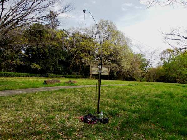 It is 7 MHz AM mobile operation of one day using this transceiver. I operated in a park about
10 minutes' walk from my house. The height of the antenna connecting the half-wave dipole of
about 20 m in length to the branch of the standing tree is low, but the VSWR has achieved 1.0.
I took only one station due to the weekday. I would like to operate radio communication from
small mountain top in future.
It is 7 MHz AM mobile operation of one day using this transceiver. I operated in a park about
10 minutes' walk from my house. The height of the antenna connecting the half-wave dipole of
about 20 m in length to the branch of the standing tree is low, but the VSWR has achieved 1.0.
I took only one station due to the weekday. I would like to operate radio communication from
small mountain top in future.