| Outline of Vacuum Tube Amplifier |
The vacuum tube amplifier is roughly divided into three kinds, that is, single amplifier, push-pull amplifier, and differential push-pull amplifier. These outlines and features are explained briefly here. In addition, I got some information from the famous homepage, "Passionate Tube Amplifier" provided by Mr. Perché to prepare this site without permission (thank you very much!).
1.Single Amplifier
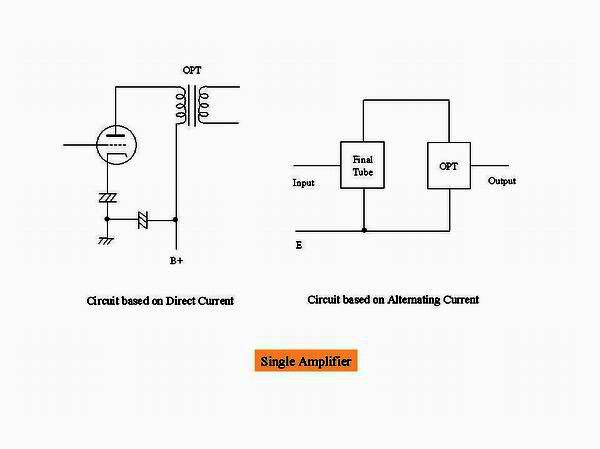 This is the simple circuit diagram which observed the composition of single amplifier from the viewpoint of
direct or alternating current circuit.
The electrolytic condenser of B power supply reduces its ripple, and performs the role which connects the
cathode of the final tube with the output power transformer through the earth in terms of the alternating
current.
The electrolytic condenser of the cathode of the final tube is connected with the ground in terms of the
alternating current (in case of the self-bias system).
This is the simple circuit diagram which observed the composition of single amplifier from the viewpoint of
direct or alternating current circuit.
The electrolytic condenser of B power supply reduces its ripple, and performs the role which connects the
cathode of the final tube with the output power transformer through the earth in terms of the alternating
current.
The electrolytic condenser of the cathode of the final tube is connected with the ground in terms of the
alternating current (in case of the self-bias system).From the above fact, the single amplifier can be said to be "the amplifier which amplifies one signal in one unbalanced amplification circuit, and carries out impedance conversion in the output power transformer".
When you put the mouse over the image, it will be
enlarged. (Same below)
2.Push-Pull Amplifier
 This is the simple circuit diagram which observed the composition of push-pull amplifier from the viewpoint of
direct or alternating current circuit.
The role of electrolytic condenser of B power supply and of the cathode of the final tube is the same as
the single amplifier.
This is the simple circuit diagram which observed the composition of push-pull amplifier from the viewpoint of
direct or alternating current circuit.
The role of electrolytic condenser of B power supply and of the cathode of the final tube is the same as
the single amplifier.
The different point from single amplifier is that it amplifies separately the signal of reverse phase and
compounds them in the output power transformer.
Even if one of the final tubes is broken down, the output will not be lost only by distortion being large.
From the above fact, the push-pull amplifier can be said to be "the amplifier which carries out impedance
conversion, after amplifying one signal using two unballanced amplification circuits with opposite phase each
other and composing them in the output power transformer".
3.Differential Push-Pull Amplifier
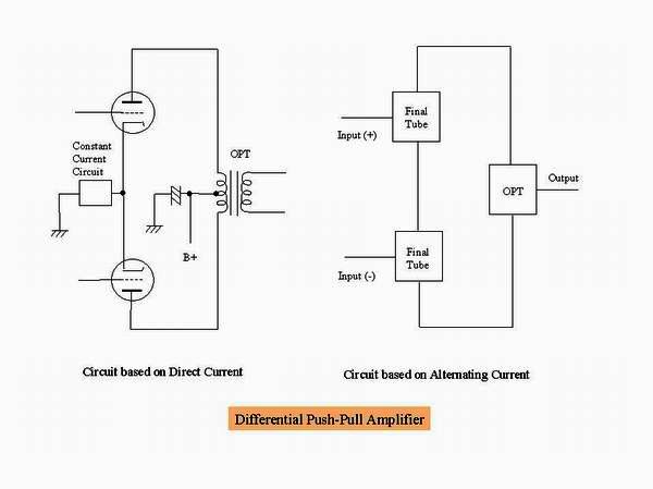 This is the simple circuit diagram which observed the composition of differential push-pull amplifier from
the viewpoint of direct or alternating current circuit. Although this resembles the circuit diagram of
push-pull amplifier, the cathode of the final tube is not connected to the ground in terms of alternating current,
but the constant current circuit is inserted which does not let the signal pass. For this reason, the electrolytic
condenser of B power supply has only the role of the ripple reduction of the power supply.
That is, the neutral point of the differential push-pull amplifier floats from the ground and therefore it is a
balanced circuit.
The output power will be lost if one of the final tubes is broken down.
This is the simple circuit diagram which observed the composition of differential push-pull amplifier from
the viewpoint of direct or alternating current circuit. Although this resembles the circuit diagram of
push-pull amplifier, the cathode of the final tube is not connected to the ground in terms of alternating current,
but the constant current circuit is inserted which does not let the signal pass. For this reason, the electrolytic
condenser of B power supply has only the role of the ripple reduction of the power supply.
That is, the neutral point of the differential push-pull amplifier floats from the ground and therefore it is a
balanced circuit.
The output power will be lost if one of the final tubes is broken down.
From the above fact, the differential push-pull amplifier can be said to be "the amplifier which amplifies
one signal with one balanced amplification circuit, and carries out impedance conversion in the
output power transformer".
Thus, although the differential push-pull amplifier bears a strong resemblance to the conventional push-pull
amplifier, it completely differs theoretically. It seems to be the reason why the sound like single
amplifier comes out in spite of the push-pull amplification.
 This is the circuit diagram of typical differential push-pull amplifier.
Since the voltage amplification stage is also differential, it is called "all-stage differential
push-pull amplifier.
The total amount of negative feedback can be adjusted by changing the
resistance (56 Ω in this case) of the first grid of 12AT7.
The necessary constant current is obtained using the constant current diode for the first stage,
and the IC called LM317 for the final stage.
The variable resistor of 20 kΩ is to perform DC balance adjustment in the final stage.
The bias of negative potential is applied to the constant current diode, in order that the diode
may not carry out constant current operation, if it is directly connected to the ground.
A voltage of -4V to -5V is required for the constant current diode at least.
This is the circuit diagram of typical differential push-pull amplifier.
Since the voltage amplification stage is also differential, it is called "all-stage differential
push-pull amplifier.
The total amount of negative feedback can be adjusted by changing the
resistance (56 Ω in this case) of the first grid of 12AT7.
The necessary constant current is obtained using the constant current diode for the first stage,
and the IC called LM317 for the final stage.
The variable resistor of 20 kΩ is to perform DC balance adjustment in the final stage.
The bias of negative potential is applied to the constant current diode, in order that the diode
may not carry out constant current operation, if it is directly connected to the ground.
A voltage of -4V to -5V is required for the constant current diode at least.
4.Feature of Various Vacuum Tube Amplifie
The feature of these three kinds of vacuum tube amplifiers is presented here dividing into the
circuit composition, the low frequency characteristic, the distortion characteristic, the maximum output
power, and the sound characteristic.
(1)Circuit composition
Item
Single
Push-pull
Differential push-pull
Phase inversion
No
Yes
Yes(From unbalance to balance)
Division of signal
No
Yes
No
Number of amplification systems
1
2
1
Transmission mode
Unbalance
Unbalance
Balance
Composition of signal
No
Yes
No
Simplicity of composition
Simple
Complicated
Somewhat complicated
(2)Low frequency characteristic
One of the weak points of the single circuit is degradation of the low frequency characteristic accompanying
the magnetic saturation by direct current magnetization of the output transformer.
Since either both push-pull circuit and differential push-pull circuit do not have this problem, the low
frequency characteristic is excellent.
Single: No good
Push-pull: Good
Differential push-pull: Good
(3)Distortion characteristic
The single circuit generates secondary distortion in spite of direct heating vacuum tube with good linearity.
Since the push-pull circuit negates secondary distortion mutually, it has good distortion characteristic.
Although the secondary distortion of the differential push-pull circuit is the same as that of the push-pull
circuit, the third distortion is larger than the push-pull circuit.
Single: Fair
Push-pull: Better
Differential push-pull: Good
(4)Channel separation characteristic
In the single circuit, since the capacity of the electrolytic condenser for high voltage of B power
supply has restriction, it becomes impossible to disregard its impedance in low frequency, the signal of opposite
side leaks through the ground, and the separation characteristic between channels gets worse.
Since the impedance of a 100μF electrolytic condenser is 160 Ω as an example in the case of 10 Hz, the leakage
proportional to the composite impedance (about 4300 Ω in case of 300B) of an output transformer and an output
tube arises.
There will be a quantity of leakage of 20 log (160/(160+4300)) = -29 dB on rough calculation (refer to the figure
below in detail).
As shown in the figure, if the impedance of electrolytic condenser were zero, there would be no cross talk between
channels.
 For improving this, it is to install by channel a decoupling circuit by a resistance and an electrolytic condenser.
In case of push-pull circuit, the signal does not flow into the electrolytic condenser in A-class amplification,
resulting a good channel separation. In case of AB-class, however, the signal flows into the electrolytic condenser,
so the channel separation gets deteriorated.
Since the differential push-pull circuit is a balanced circuit, the signal does not flow through the electrolytic
condenser for high voltage of B power supply, resulting an excellent channel separation.
For improving this, it is to install by channel a decoupling circuit by a resistance and an electrolytic condenser.
In case of push-pull circuit, the signal does not flow into the electrolytic condenser in A-class amplification,
resulting a good channel separation. In case of AB-class, however, the signal flows into the electrolytic condenser,
so the channel separation gets deteriorated.
Since the differential push-pull circuit is a balanced circuit, the signal does not flow through the electrolytic
condenser for high voltage of B power supply, resulting an excellent channel separation.
Single: Fair
Push-pull: Good
Differential push-pull: Better
(5)Maximum output power
The maximum output power of single circuit is theoretically 50% of plate loss of the output tube, but 25%-40%
is common in practice.
In the push-pull circuit, more than two times of single circuit is obtained by the class A, and 3 to 5 times
by the class AB.
However, in the differential push-pull circuit, it becomes about 1.5 to 2 times of the single circuit.
I think that the good sound is the charm of the differential push-pull circuit rather than low output power.
Single: Fair
Push-pull: Better
Differential push-pull: Good
(6)Sound characteristic
The single amplifier creates a peculiar sound which energy concentrated in the middle frequency range.
Although the push-pull amplifier makes an ordinary sound from low to high frequency range, it is thought that its sound
does not come out in front a little.
Since the differential push-pull amplifier is excellent in channel separation, it creates the acoustic field with high
density in sense of stability.
The bass has a peculiar feeling of power, and I feel that its sound comes out in front also in case of small volume.
Moreover, since the residual noise is very small, even if I bring my ear close to the speaker, any noise can hardly
be heard.
Single: Good
Push-pull: Good
Differential push-pull: Better