| 811A Single Dynamic Coupled Amplifier |
As I got a pair of new RCA 811A by chance, I made a dynamic coupled power amplifier to hear the sound produced by the thorium tungsten heater. It is said that the sound of 811A is so refreshing especially in the high audio frequency. The problem is its heater which needs 6.3V 4A. Therefore I bought a big power transformer with two coils of 6.3V 5A.
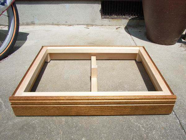 As the metal chassis is very expensive for me, I made it using wood and aluminum panels. The thickness of
aluminum panel is only 1.5mm. So it is supported at the center with a wood foot.
As the metal chassis is very expensive for me, I made it using wood and aluminum panels. The thickness of
aluminum panel is only 1.5mm. So it is supported at the center with a wood foot.If you put the mouse over the image, it will be
enlarged. (Same below)
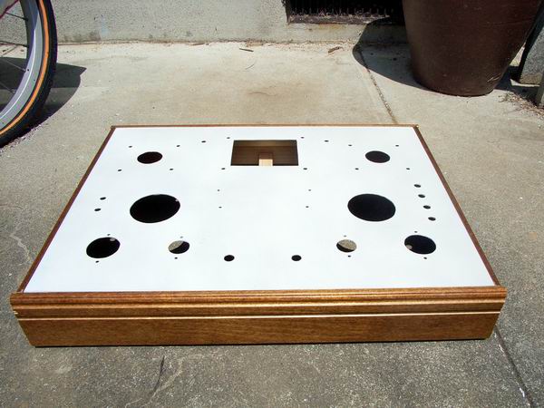 This is the aluminum panel after boring of holes and painting with white lacquer. The dimension of panel
is 400 (W), 300 (D), 1.5 (T) mm.
This is the aluminum panel after boring of holes and painting with white lacquer. The dimension of panel
is 400 (W), 300 (D), 1.5 (T) mm.
 This is the upper view of the amplifier. Main parts are:
AC transformer: 250/350V 300mA, 6.3V 5A x 2, 5V 4A made by SEL
Choke coil: 5H 300mA made by SEL
Output transformer: FW-20S made by Tango
Voltage amplification: RCA 5751 x 2
Driver amplification: Telefunken EL34 x 2
Final amplification: RCA 811A x 2
 This is the rear view of the 811A amplifier. As the installation position of speaker terminals was changed
from the rear to side, the useless space occurred at the back of output transformer.
This is the rear view of the 811A amplifier. As the installation position of speaker terminals was changed
from the rear to side, the useless space occurred at the back of output transformer.
 This is the inside view of the amplifier. The tube of 811A is installed under the chassis by 25mm.
The bridge rectifier for heater voltage is directly contacted to aluminum chassis to radiate its heat.
This is the inside view of the amplifier. The tube of 811A is installed under the chassis by 25mm.
The bridge rectifier for heater voltage is directly contacted to aluminum chassis to radiate its heat.
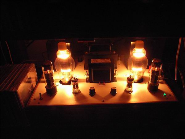 It is very pleasant to watch the light of thorium-tungsten heater. But its heat is so large, not suitable in
the summer.
I knew that the green lamp to show power-on is a useless thing.
It is very pleasant to watch the light of thorium-tungsten heater. But its heat is so large, not suitable in
the summer.
I knew that the green lamp to show power-on is a useless thing.
 These are vacuum tubes used, from the left, Telefunken EL34, RCA 811A, RCA 5751. The beauty of lines of 811A
is wonderful as the rumors say.
These are vacuum tubes used, from the left, Telefunken EL34, RCA 811A, RCA 5751. The beauty of lines of 811A
is wonderful as the rumors say.
 This is the circuit diagram of the amplifier. As this type of vacuum tube for transmitter needs positive
grid bias, the self-bias circuit can not be applied. Therefore I applied the famous driving way,
dynamic coupled circuit. The plate voltage of 811A is 390V under the plate current of 100mA. The residual
noise is 1.0mV, which is a little bit large.
This is the circuit diagram of the amplifier. As this type of vacuum tube for transmitter needs positive
grid bias, the self-bias circuit can not be applied. Therefore I applied the famous driving way,
dynamic coupled circuit. The plate voltage of 811A is 390V under the plate current of 100mA. The residual
noise is 1.0mV, which is a little bit large.
When the power is on I heard the noise of big hum for several seconds. To solve this problem, I
installed a time delay circuit of 20 seconds using two transistors, 20k/5k resistors and 6,600μF
condenser. Due to this delay circuit, now any noise can not be heard.
 This is the frequency response of 811A amplifier at the output power of 1 W. The performace of low frequency
is not so good in comparison with high frequency. The figure of overall negative feedback is 5.4dB.
Although the figure of damping factor is only 1.5, the sound produced is very refreshing and impressive as
same as the rumor.
This is the frequency response of 811A amplifier at the output power of 1 W. The performace of low frequency
is not so good in comparison with high frequency. The figure of overall negative feedback is 5.4dB.
Although the figure of damping factor is only 1.5, the sound produced is very refreshing and impressive as
same as the rumor.
 This is the input vs. output characteristic of 811A amplifier.
The form of sine wave begins to be distorted at around 10W of output power when measured by the
oscilloscope. The total voltage gain is about 16 times.
This is the input vs. output characteristic of 811A amplifier.
The form of sine wave begins to be distorted at around 10W of output power when measured by the
oscilloscope. The total voltage gain is about 16 times.
 This is the distortion rate characteristic of 811A amplifier. The deterioration of the rate in the low
frequency seems to be caused by the thermal noise.
The residual noise is 1.0mV, which is a little bit large.
This is the distortion rate characteristic of 811A amplifier. The deterioration of the rate in the low
frequency seems to be caused by the thermal noise.
The residual noise is 1.0mV, which is a little bit large.
 This is the channel separation characteristic of 811A amplifier. Because the software of WaveSpectra for personal
computer is used, the maximum frequency is up to 20kHz. This curve is comparatively good for the single-ended
amplifier.
This is the channel separation characteristic of 811A amplifier. Because the software of WaveSpectra for personal
computer is used, the maximum frequency is up to 20kHz. This curve is comparatively good for the single-ended
amplifier.
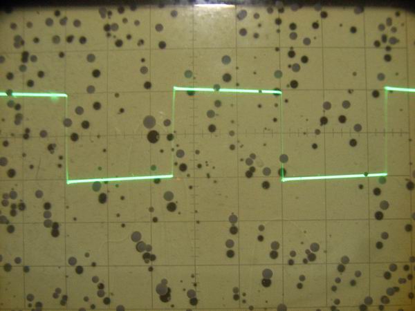
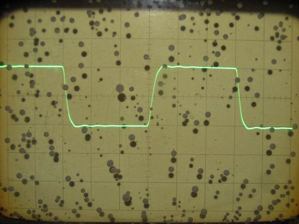
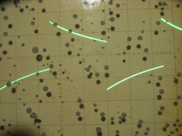 These are the responses of square wave form of 811A amplifier at 2Vp-p. From the top, 100Hz, 1kHz and
10kHz, which are all normal, I believe.
These are the responses of square wave form of 811A amplifier at 2Vp-p. From the top, 100Hz, 1kHz and
10kHz, which are all normal, I believe.