| 40KG6A Hybrid SEPP DC OTL Amplifier |
I wanted to make a vacuum tube OTL (Output Transformer Less) amplifier at once, but thinking about the problem such as complicated circuit, high stability required, large power consumption in proportion to its output power, and many vacuum tubes of the same characteristics are required, I hesitated to make it. I understand that the vacuum tube DC amplifier has the risk of destroying the speaker, but still I want to hear that sound strongly. Someday the MJ Magazine introduced a hybrid SEPP DC OTL amplifier that uses semiconductors for the driving stage and obtains output power of 20 W with only 4 vacuum tubes. From this article I challenged to make this amplifier expecting that it would be possible to build it with a cost of 2 pieces of large OPT. In the audio world, it is said that this kind of DC amplifier is impossible to obtain the original sound if used parts and wiring method are changed even a little. But I changed arbitrarily many points from the original with my carefree personality as shown below.
1. Isolation transformer was used because it is scary of electric shock in case of PTL (Power Transformer Less).
2. 12V heater transformer was used for DC ± 14V power supply.
3. Vacuum tube socket and plate cap were used.
4. Cheap carbon and oxidized metal film resistors were used.
5. Phase compensation capacitor used cheap ceramic.
6. Delayed relay for speaker protection circuit was used
7. Manual switched rush current countermeasure was changed to delayed relay.
8. 1Ω resistor for plate current measurement was inserted.
9. Screen grid resistor was changed from 220 Ω to 1 kΩ.
10. 50 kΩ volume was inserted at amplifier input.
11. Forced discharge of residual charge by switch was changed to slow discharge by resistance.
12. Small heat sink and iron plate were attached to all high-voltage transistors.
13. Simple cooling fan was installed on chassis.
14. Plate current monitoring meter was installed.
15. Heater resistor with heat sink was installed on chassis from inside.
 I found two pairs of 40KG6A for just 10,000 yen in the net auction and bid successfully. Although the
manufacturer name of PHILIPS ECG is written in the box, there is no stamp on the tube surface. I also
bought plate cap of 6 mm for price of 200 yen per piece. The original author of this amplifier solders
directly to the pin without using the socket and plate cap, but I can not do such a thing. I believe
that vacuum tubes have variations in lifetime and characteristics and should be replaced.
I found two pairs of 40KG6A for just 10,000 yen in the net auction and bid successfully. Although the
manufacturer name of PHILIPS ECG is written in the box, there is no stamp on the tube surface. I also
bought plate cap of 6 mm for price of 200 yen per piece. The original author of this amplifier solders
directly to the pin without using the socket and plate cap, but I can not do such a thing. I believe
that vacuum tubes have variations in lifetime and characteristics and should be replaced.
If you put the mouse over the image, it will be
enlarged. (Same below)
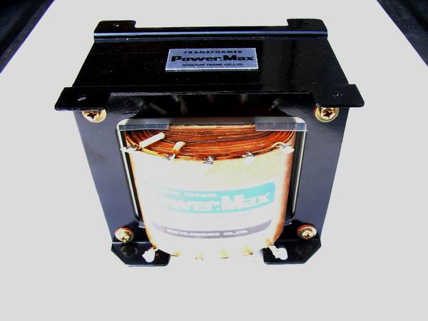 As the circuit diagram introduced in the MJ magazine corresponds not only to OTL but also to PTL (Power
Transformer Less), further cost reduction is aimed at. However, PTL worries about not only the danger
of electric shock, but also bad affect to the CD player, tuner, preamplifier and so on connected to
this amplifier. For that reason, I used 1:1 isolation transformer although it will cost a little.
Since the heater of 40KG6A is also supplied from the isolation transformer, the capacity of the
transformer is 200 W which is very large, but cost performance is good because it can be bought at
less than 10,000 yen compared to general power transformer.
As the circuit diagram introduced in the MJ magazine corresponds not only to OTL but also to PTL (Power
Transformer Less), further cost reduction is aimed at. However, PTL worries about not only the danger
of electric shock, but also bad affect to the CD player, tuner, preamplifier and so on connected to
this amplifier. For that reason, I used 1:1 isolation transformer although it will cost a little.
Since the heater of 40KG6A is also supplied from the isolation transformer, the capacity of the
transformer is 200 W which is very large, but cost performance is good because it can be bought at
less than 10,000 yen compared to general power transformer.
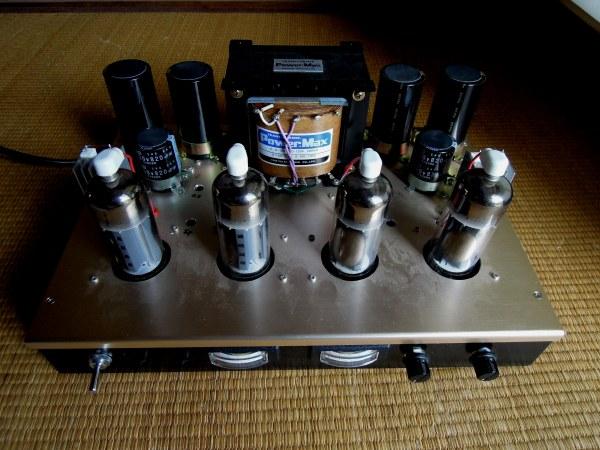
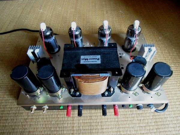
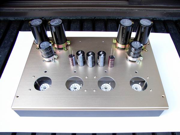 I, poor man, usually made the chassis by processing cheap aluminum plate and wood, but considering my
life expectancy and this tube amplifier to be the last, I bought TAKACHI made metal case (W: 370, D:
255, H: 58 mm) at about 10,000 yen. Because the thickness of the top plate is 2 mm, I made hard work
making beans in my hands due to poor condition of tools. The features of vacuum tube OTL amplifier
are low voltage and large current, and large capacity electrolytic capacitor is necessary to prevent
ripple after rectification. The photo shows all of electrolytic capacitors.
I, poor man, usually made the chassis by processing cheap aluminum plate and wood, but considering my
life expectancy and this tube amplifier to be the last, I bought TAKACHI made metal case (W: 370, D:
255, H: 58 mm) at about 10,000 yen. Because the thickness of the top plate is 2 mm, I made hard work
making beans in my hands due to poor condition of tools. The features of vacuum tube OTL amplifier
are low voltage and large current, and large capacity electrolytic capacitor is necessary to prevent
ripple after rectification. The photo shows all of electrolytic capacitors.
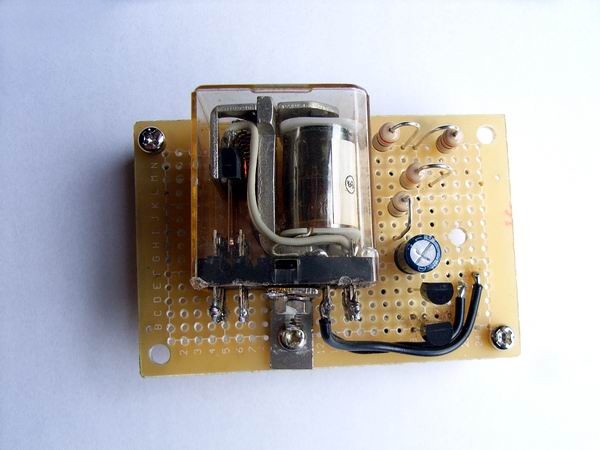
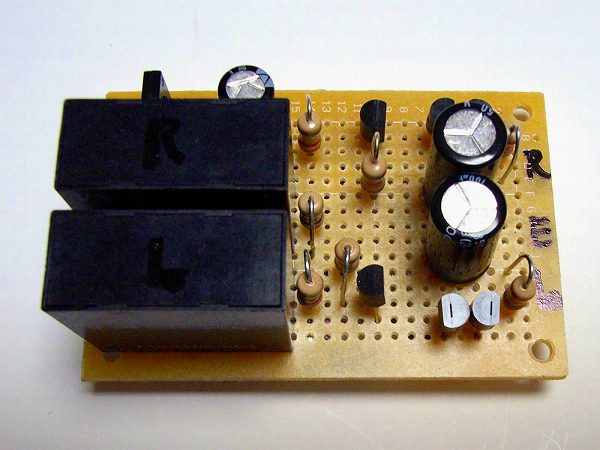 Since the DC output voltage flows directly to the speaker of the OTL DC amplifier, the speaker
protection circuit is indispensable. The photograph is a protection circuit produced using a
small printed circuit board.
Since the DC output voltage flows directly to the speaker of the OTL DC amplifier, the speaker
protection circuit is indispensable. The photograph is a protection circuit produced using a
small printed circuit board.
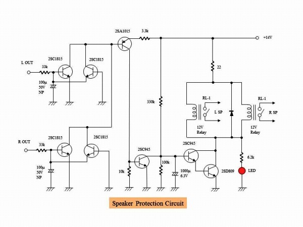 It is the circuit diagram of the speaker protection circuit. In the MJ magazine's production example,
an electronic protection circuit using MOS-FET and digital OP amplifier was used, but I made my own
classic protection circuit by relay because I am an analog man. Normally, a timer IC called "555" is
used but I will make a simple timer using CR time constant. The amplifier is connected to the speaker
in about 40 seconds after the vacuum tube stabilizes after turning on the power supply. The calculated
delay time is 43 seconds, which is almost the same as the theoretical operation. In this state, if the
offset voltage of the output terminal exceeds about ± 0.6 V, the speaker is disconnected. When the
offset voltage becomes ± 0.6 V or less, the speaker is connected again after about 40 seconds.
It is the circuit diagram of the speaker protection circuit. In the MJ magazine's production example,
an electronic protection circuit using MOS-FET and digital OP amplifier was used, but I made my own
classic protection circuit by relay because I am an analog man. Normally, a timer IC called "555" is
used but I will make a simple timer using CR time constant. The amplifier is connected to the speaker
in about 40 seconds after the vacuum tube stabilizes after turning on the power supply. The calculated
delay time is 43 seconds, which is almost the same as the theoretical operation. In this state, if the
offset voltage of the output terminal exceeds about ± 0.6 V, the speaker is disconnected. When the
offset voltage becomes ± 0.6 V or less, the speaker is connected again after about 40 seconds.
 The vacuum tube OTL amplifier requires a large capacity electrolytic capacitor. When power is turned on,
two pairs of 9,000 μF start charging and the power fuse jumps due to rush current. The photograph is a
rush current mitigation circuit created using a small printed circuit board. This prevents fuses from
cutting.
The vacuum tube OTL amplifier requires a large capacity electrolytic capacitor. When power is turned on,
two pairs of 9,000 μF start charging and the power fuse jumps due to rush current. The photograph is a
rush current mitigation circuit created using a small printed circuit board. This prevents fuses from
cutting.
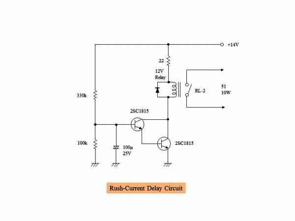 It is the circuit diagram of the rush current relaxing circuit. A relay circuit was installed so that it
short-circuits the resistor of 51 Ω 10 W approximately 4 seconds after the power was turned on. It is
simple delay circuit that utilizes the charging time of the electrolytic capacitor. Calculated delay
time is 4.3 seconds, so it is almost as calculated.
It is the circuit diagram of the rush current relaxing circuit. A relay circuit was installed so that it
short-circuits the resistor of 51 Ω 10 W approximately 4 seconds after the power was turned on. It is
simple delay circuit that utilizes the charging time of the electrolytic capacitor. Calculated delay
time is 4.3 seconds, so it is almost as calculated.
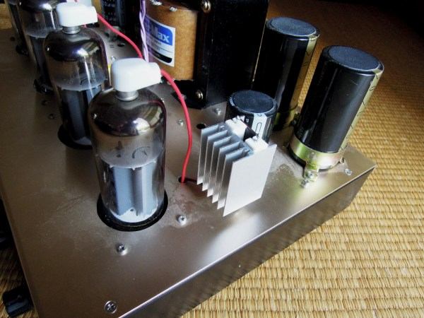
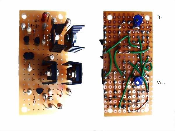 It is the board of driving stage composed of semiconductor elements. I installed two semi-fixed volumes
on the backside of the board so that the adjustment of output offset voltage and idling current can be
made through the holes on the chassis. All high-voltage transistors with extreme rise in temperature
attached small heat sink (since it still gets hot, I added small iron plate later). Three-dimensional
intersection wiring can be seen because element arrangement is somewhat bad but let's forgive.
It is the board of driving stage composed of semiconductor elements. I installed two semi-fixed volumes
on the backside of the board so that the adjustment of output offset voltage and idling current can be
made through the holes on the chassis. All high-voltage transistors with extreme rise in temperature
attached small heat sink (since it still gets hot, I added small iron plate later). Three-dimensional
intersection wiring can be seen because element arrangement is somewhat bad but let's forgive.
To tell the truth, it took a lot of labor to make this board. Both of these two boards are second
generations. It was reworked because many elements were destroyed during the test of the amplifier.
Since + 130V, -260V, -14V are supplied to the semiconductor circuit, destruction when short-circuiting
is fatal. For elderly man close to 70 years old, it is very difficult to prepare substrates for
semiconductor devices, so I would like to do this last. To be honest, when two substrates broke and it
was necessary to rebuild, I thought of giving up making the OTL amplifier. But since other parts look
pretty, I resumed production with a cooling period of about two weeks. We should not give up anything.
 It is the front of the amplifier. It is equipped with a green LED lamp for checking the main power
supply, a red LED lamp for checking the operation of the speaker protection circuit, and an ammeter
for measuring the plate current. A series resistance is put in the ammeter, and the voltage drop of
the 1 Ω resistor inserted in the plate circuit is measured and used as the ammeter of full scale
400 mA. 1 Ω is inserted in the upper vacuum tube, but if the output offset voltage is 0 V, the
same plate current flows in the lower tube.
It is the front of the amplifier. It is equipped with a green LED lamp for checking the main power
supply, a red LED lamp for checking the operation of the speaker protection circuit, and an ammeter
for measuring the plate current. A series resistance is put in the ammeter, and the voltage drop of
the 1 Ω resistor inserted in the plate circuit is measured and used as the ammeter of full scale
400 mA. 1 Ω is inserted in the upper vacuum tube, but if the output offset voltage is 0 V, the
same plate current flows in the lower tube.
 It is the back of the amplifier. Check terminal of output offset voltage is equipped. The case of
the large capacity electrolytic capacitor is connected to the earth side terminal and there is no
problem in the case of the minus earth. But in the case of the plus earth it takes a negative high
voltage to the case, so it is necessary to pay attention to electric shock and short-circuited.
For this reason, I pasted vinyl cloth on the top of the case of the condenser.
It is the back of the amplifier. Check terminal of output offset voltage is equipped. The case of
the large capacity electrolytic capacitor is connected to the earth side terminal and there is no
problem in the case of the minus earth. But in the case of the plus earth it takes a negative high
voltage to the case, so it is necessary to pay attention to electric shock and short-circuited.
For this reason, I pasted vinyl cloth on the top of the case of the condenser.
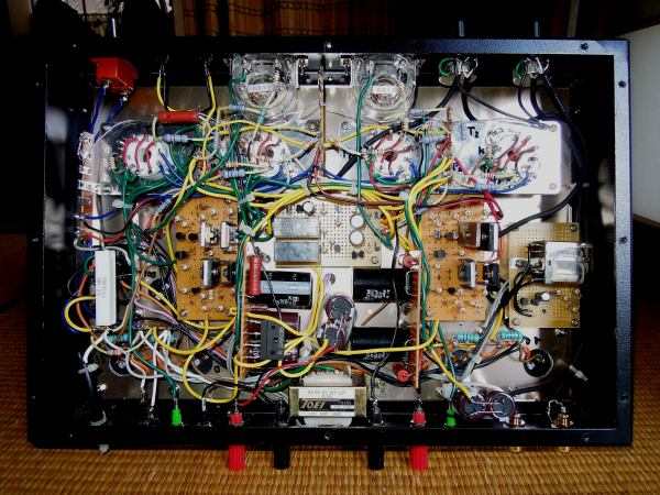 It is inside the amplifier. I experienced this complex vacuum tube amplifier for the first time. I
am worried that the semiconductor device can withstand high temperature in the summer in the state
where the inside of the chassis is almost full. Since 40KG6A excludes the cathode and the electrode
comes out of the two legs, it connects twice with lead wire in order to reduce even slight contact
failure of the socket. In the DC amplifier, imbalance due to contact failure can cause a major
accident. Since the high-voltage transistor becomes very hot, 2 mm thick iron plate was sandwiched
between transistor and heat sink.
It is inside the amplifier. I experienced this complex vacuum tube amplifier for the first time. I
am worried that the semiconductor device can withstand high temperature in the summer in the state
where the inside of the chassis is almost full. Since 40KG6A excludes the cathode and the electrode
comes out of the two legs, it connects twice with lead wire in order to reduce even slight contact
failure of the socket. In the DC amplifier, imbalance due to contact failure can cause a major
accident. Since the high-voltage transistor becomes very hot, 2 mm thick iron plate was sandwiched
between transistor and heat sink.
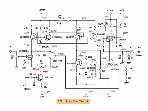 Since the idle current is 175 mA and the vacuum tube is lightly used (60% of the maximum plate loss),
the maximum output is about 8 W. In the original of MJ magazine, It got 20 W by running 270 mA, but I
can not imitate such horrible things and I do not need 20 W for output as well.
How to adjust the offset voltage and idling current: First set 500 Ω volume to the left and 50 Ω
volume to the middle. This will minimize the idling current of 40KG6A. The plate current changes
depending on the resistance value of 3 kΩ connected in series with 500 Ω volume, but it hardly
flows. In this state, slowly turn the volume of 50 Ω and adjust the output offset voltage to 0 V.
Then slowly turn the volume of 500 Ω right to increase the plate current. Since the offset voltage
changes, set it to 0 V with a volume of 50 Ω. Once these operations are repeated and the plate
current can be set to the prescribed plate current, set the offset voltage to the minimum (OK if it
is less than ± 10 mV).
Since the idle current is 175 mA and the vacuum tube is lightly used (60% of the maximum plate loss),
the maximum output is about 8 W. In the original of MJ magazine, It got 20 W by running 270 mA, but I
can not imitate such horrible things and I do not need 20 W for output as well.
How to adjust the offset voltage and idling current: First set 500 Ω volume to the left and 50 Ω
volume to the middle. This will minimize the idling current of 40KG6A. The plate current changes
depending on the resistance value of 3 kΩ connected in series with 500 Ω volume, but it hardly
flows. In this state, slowly turn the volume of 50 Ω and adjust the output offset voltage to 0 V.
Then slowly turn the volume of 500 Ω right to increase the plate current. Since the offset voltage
changes, set it to 0 V with a volume of 50 Ω. Once these operations are repeated and the plate
current can be set to the prescribed plate current, set the offset voltage to the minimum (OK if it
is less than ± 10 mV).
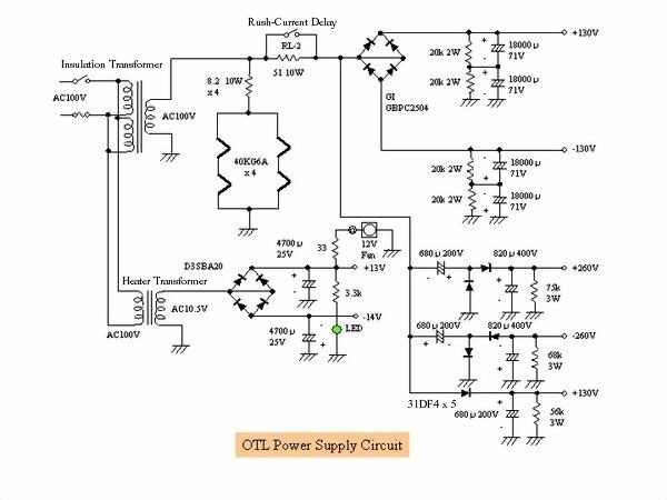 This is a circuit diagram of the power supply section. It is equipped with a resistor that slowly
discharges the residual electric charge when the power is off. I used a 12V heater transformer on
hand because it is ± 14V power supply. Actually, because the load is light, when using the AC 12 V
terminal the output becomes DC 17 V and the offset voltage adjustment was unstable so we used the
AC 10 V terminal. Due to the internal resistance of the isolation transformer, the DC voltage is
5 V to 10 V lower than the PTL case.
This is a circuit diagram of the power supply section. It is equipped with a resistor that slowly
discharges the residual electric charge when the power is off. I used a 12V heater transformer on
hand because it is ± 14V power supply. Actually, because the load is light, when using the AC 12 V
terminal the output becomes DC 17 V and the offset voltage adjustment was unstable so we used the
AC 10 V terminal. Due to the internal resistance of the isolation transformer, the DC voltage is
5 V to 10 V lower than the PTL case.
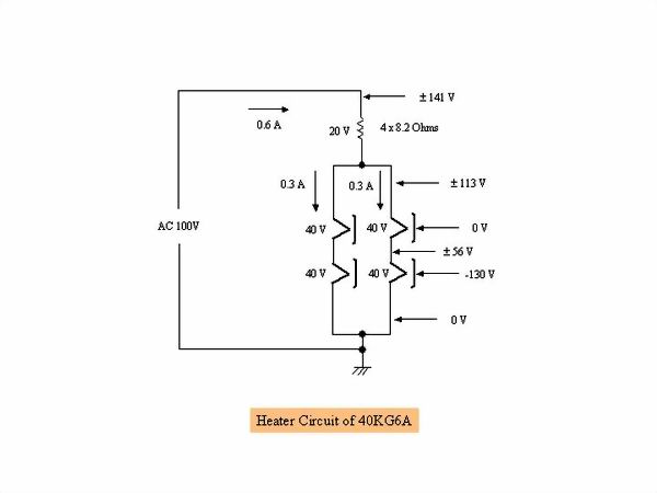 It is a heater circuit of 40KG6A. What is important here is the problem of the withstand voltage
between the heater and the cathode. The withstand voltage of this sphere is ± 250 V, which is a
large value, considerable consideration is necessary for the wiring of the heater. -130 V is always
applied to the cathode of the lower sphere of the SEPP circuit. Therefore, when the cold side of
the heater of the lower tube is dropped to ground, the electric potential on the hot side becomes
± 56 V (1.41 times of AC 40 V), the potential difference from the cathode becomes -74 V to -186 V,
and it is within the withstand voltage ± 250 V. On the other hand, since the potential of the
cathode of the upper tube is around 0 V and the potential of the hot side of the heater is ±
113 V (1.41 times of AC 80 V), the potential difference from the cathode is + 113 V to -113 V,
which is within the withstand voltage ± 250 V. In other words, it is dangerous to make a mistake
in the place to drop the heater to earth. Never ground the 4 x 8.2 Ω resistor side that will bear
the AC 20 V voltage.
It is a heater circuit of 40KG6A. What is important here is the problem of the withstand voltage
between the heater and the cathode. The withstand voltage of this sphere is ± 250 V, which is a
large value, considerable consideration is necessary for the wiring of the heater. -130 V is always
applied to the cathode of the lower sphere of the SEPP circuit. Therefore, when the cold side of
the heater of the lower tube is dropped to ground, the electric potential on the hot side becomes
± 56 V (1.41 times of AC 40 V), the potential difference from the cathode becomes -74 V to -186 V,
and it is within the withstand voltage ± 250 V. On the other hand, since the potential of the
cathode of the upper tube is around 0 V and the potential of the hot side of the heater is ±
113 V (1.41 times of AC 80 V), the potential difference from the cathode is + 113 V to -113 V,
which is within the withstand voltage ± 250 V. In other words, it is dangerous to make a mistake
in the place to drop the heater to earth. Never ground the 4 x 8.2 Ω resistor side that will bear
the AC 20 V voltage.
 Vacuum tube OTL amplifier has a quite heat, especially the condition is bad in summer. Simply calculate
the calorific value, the heater generates 100 V x 0.3 A x 2 = 60 W, the plate loss 260 V x 0.175 A x 2 =
91 W, even if the heat generation of the semiconductor device is ignored, the total heat generation will
be 151 W. It is almost like a small electric heater. Therefore I created a simple cooling system using 8
cm cooling fan for PC. To reduce noise, 12V fan is operated at 9V and it is simply placed on the chassis.
When it is unnecessary such as in the winter, you can unplug it and remove it. I do not know the degree
of effect until it is summer. The offset voltage is also stable and is within ± 10 mV. The plate current
also increases slowly and it stabilizes in about 5 minutes.
Vacuum tube OTL amplifier has a quite heat, especially the condition is bad in summer. Simply calculate
the calorific value, the heater generates 100 V x 0.3 A x 2 = 60 W, the plate loss 260 V x 0.175 A x 2 =
91 W, even if the heat generation of the semiconductor device is ignored, the total heat generation will
be 151 W. It is almost like a small electric heater. Therefore I created a simple cooling system using 8
cm cooling fan for PC. To reduce noise, 12V fan is operated at 9V and it is simply placed on the chassis.
When it is unnecessary such as in the winter, you can unplug it and remove it. I do not know the degree
of effect until it is summer. The offset voltage is also stable and is within ± 10 mV. The plate current
also increases slowly and it stabilizes in about 5 minutes.
 Initially, 40KG6A heater pressure reduction resistors (8.2 Ω 10 W 4 pieces) were housed in the
chassis, but the inside of the chassis became very hot as the 12 W heater was inside, so a heat
sink was attached to the resistance I attached it externally later. I placed it the same way on
the left and right. The temperature rise inside the chassis is improved considerably with this.
Initially, 40KG6A heater pressure reduction resistors (8.2 Ω 10 W 4 pieces) were housed in the
chassis, but the inside of the chassis became very hot as the 12 W heater was inside, so a heat
sink was attached to the resistance I attached it externally later. I placed it the same way on
the left and right. The temperature rise inside the chassis is improved considerably with this.
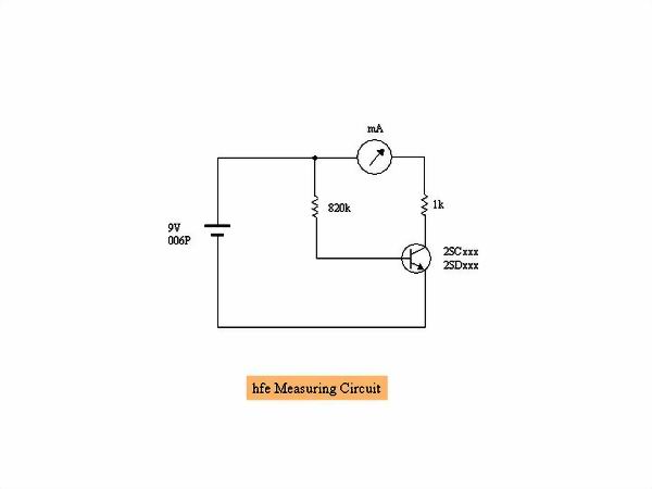 I accidentally destroyed several transistors by mistake, but although I can confirm the life and
death with a tester, I am worried about whether it really can be used. Therefore, I introduce a
circuit that measures simply DC current amplification factor (hfe). For large transistors it is
difficult to measure the correct hfe but it is good to know the approximate value. The principle
is to measure the collector current with 0.01 mA flowing in the base and divide it by base current
becomes the hfe. For example, in case of 1 mA, the hfe will be 100. For PNP type it is necessary
to invert the polarity of the battery (the runout of the ammeter is reversed).
I accidentally destroyed several transistors by mistake, but although I can confirm the life and
death with a tester, I am worried about whether it really can be used. Therefore, I introduce a
circuit that measures simply DC current amplification factor (hfe). For large transistors it is
difficult to measure the correct hfe but it is good to know the approximate value. The principle
is to measure the collector current with 0.01 mA flowing in the base and divide it by base current
becomes the hfe. For example, in case of 1 mA, the hfe will be 100. For PNP type it is necessary
to invert the polarity of the battery (the runout of the ammeter is reversed).
 It is the amplitude frequency characteristic at 1 W output. It was OTL so I expected more smooth
high frequency characteristic, but it was surprising. I think that the characteristics of the
semiconductor driver section appeared.
It is the amplitude frequency characteristic at 1 W output. It was OTL so I expected more smooth
high frequency characteristic, but it was surprising. I think that the characteristics of the
semiconductor driver section appeared.
 It is input to output characteristic measured at a frequency of 1 kHz. The characteristic curve
begins to turn from about 8 W. If exceeding 10 W, the plate current will exceed 400 mA and the
meter will shake off, so measurement should be done briefly. The amplifier gain is 14 times, the
residual noise is 0.25 mV, the damping factor is 6.8 and it is sufficient as a tube amplifier.
It is input to output characteristic measured at a frequency of 1 kHz. The characteristic curve
begins to turn from about 8 W. If exceeding 10 W, the plate current will exceed 400 mA and the
meter will shake off, so measurement should be done briefly. The amplifier gain is 14 times, the
residual noise is 0.25 mV, the damping factor is 6.8 and it is sufficient as a tube amplifier.
 It is distortion characteristic. If the output is increased, the plate current will increase, the
Ip meter will shake out and exceed the maximum plate loss, so long as I can not measure the distortion
rate, only up to 8 W I can take data. It is unusual curve that I have not seen in the past, but is
it characteristic of the OTL amplifier that the increase in distortion rate once ends from around
4 W or is it a feature of the pentode output tube? In any case, the distortion rate falls within 0.5%
at any frequency when the output is less than 8 W, which is a satisfactory value.
It is distortion characteristic. If the output is increased, the plate current will increase, the
Ip meter will shake out and exceed the maximum plate loss, so long as I can not measure the distortion
rate, only up to 8 W I can take data. It is unusual curve that I have not seen in the past, but is
it characteristic of the OTL amplifier that the increase in distortion rate once ends from around
4 W or is it a feature of the pentode output tube? In any case, the distortion rate falls within 0.5%
at any frequency when the output is less than 8 W, which is a satisfactory value.
 It is separation characteristics of Lch to Rch at 1 W output. Since there was no data on the
separation characteristics of the hybrid DC OTL amplifier, I was interested and measured it.
I measured with the same PC software WaveSpectra as the distortion factor characteristic.
The result is a good characteristic in spite of not performing the decoupling process between
the left and right channels, and there is no deterioration of the separation especially in the
low range. It may be influenced that the power supply of the driver stage and the final stage
are completely independent. -120 dB is excellent value less than the noise level and waveform
can not be checked with WaveSpectra.
It is separation characteristics of Lch to Rch at 1 W output. Since there was no data on the
separation characteristics of the hybrid DC OTL amplifier, I was interested and measured it.
I measured with the same PC software WaveSpectra as the distortion factor characteristic.
The result is a good characteristic in spite of not performing the decoupling process between
the left and right channels, and there is no deterioration of the separation especially in the
low range. It may be influenced that the power supply of the driver stage and the final stage
are completely independent. -120 dB is excellent value less than the noise level and waveform
can not be checked with WaveSpectra.
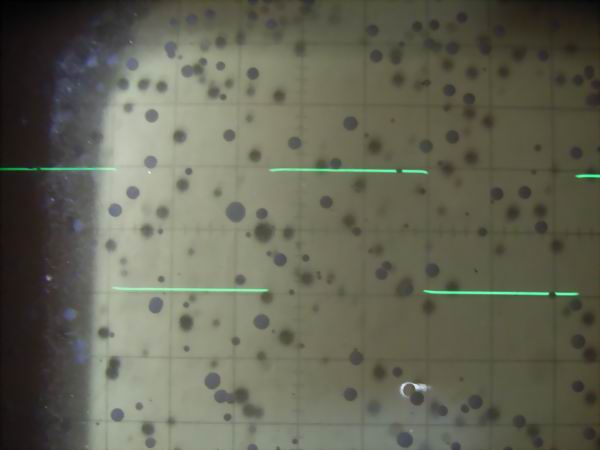
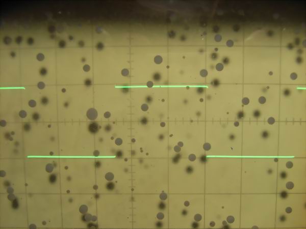
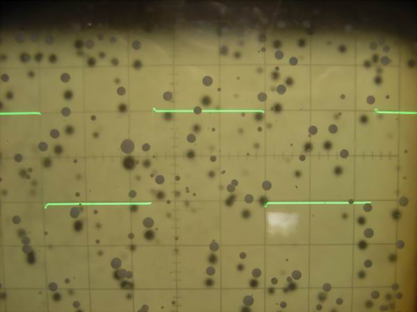
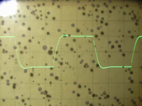
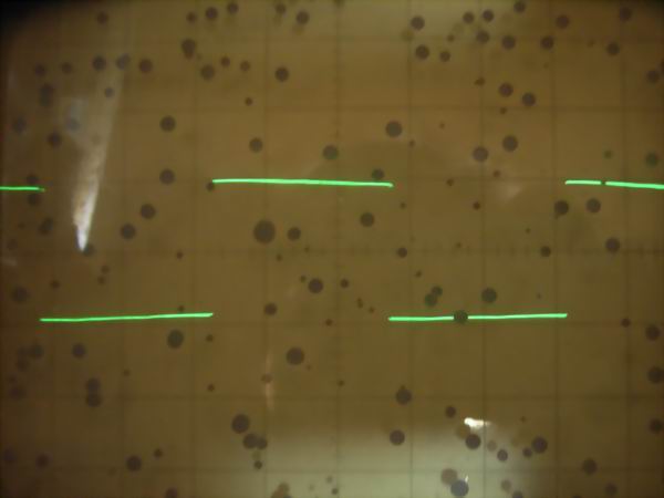 It is the square wave response waveform of 40KG6A SEPP DC OTL amplifier at 2 Vp-p. From the
top are 10 Hz, 100 Hz, 1 kHz, 10 kHz, 100 kHz. As it is a DC amplifier, it is estimated that
only small sag is seen even at 10 Hz and low frequency has flat frequency characteristic up
to direct current. Although there is small overshoot at 10 kHz in the high range, there is
no big problem. At 100 kHz, the rise time is slightly bad, but it will be excellent for
tube amplifier.
It is the square wave response waveform of 40KG6A SEPP DC OTL amplifier at 2 Vp-p. From the
top are 10 Hz, 100 Hz, 1 kHz, 10 kHz, 100 kHz. As it is a DC amplifier, it is estimated that
only small sag is seen even at 10 Hz and low frequency has flat frequency characteristic up
to direct current. Although there is small overshoot at 10 kHz in the high range, there is
no big problem. At 100 kHz, the rise time is slightly bad, but it will be excellent for
tube amplifier.
◎Impression of hybrid SEPP DC OTL amplifier:
It is the first time to listen to the sound from the DC OTL amplifier, but I think that it has come
out well from bass to treble. Especially the attack sound of the drums is wonderful. Although the
speaker protection circuit operates normally, it may be influenced by listening with a feeling of
tension. Since I use vacuum tubes lightly, the maximum output is around 8 W but it is enough in
my audio environment. I can not hear any hum. In terms of cost, it was 50,000 yen instead of 30,000
yen, because the insulation transformer, input volume, vacuum tube socket, plate cap, plate current
monitoring meter etc. were used. But I think that it is about a half compared with the OPT type
vacuum tube amplifier. Its weight also came from the insulation transformer only, so it is convenient
for senior people. It has been several years since I started using this amplifier, but the operation
is quite stable. The plate current of the final stage tube does not change at 175 mA, and the delayed
relay connecting the amplifier to the speaker after turning on the power also works exactly in 30
seconds.
◎Addendum: Addition of capacitor for DC cut to the amplifier output section
Although the DC voltage of the amplifier output is stable at ± a few mV, it is scary to connect
directly to an important JBL large speaker, so I inserted an electrolytic capacitor of 50 V 4,700
μF and a film capacitor of 50 V 0.47 μF. With the feeling I heard with my poor ear, the sound
quality deterioration due to condenser insertion is not recognized. With this, I think that it is
possible to prevent accidental damage of the speaker in the unlikely event so I can listen with
confidence.