| UV211 Single Amplifier |
At the age of 70 years old, making a vacuum tube amplifier has finally come to an end. As a result of searching for vacuum tube saying "This is the last vacuum tube amplifier of my life", I judged that UV211 is the most suitable. There is no complaint in size, shape, linearity and so on. However, it is said that it is impossible to obtain good result unless the plate voltage close to 1,000 V is applied, and if I get an electric shock, I will die so I have stepped on it so far. Now that the life expectancy has reached 10 years, I decided to make it beyond the shock of electrocution. I bought new parts other than the power transformer and choke coil, but it was completed with less budget (50,000 yen) than the price of one Tango or Tamura output transformer or power transformer due to the sorrow of the poor man.
By the way, the most important result is truly the sound of vacuum tube. Middle and high area is shining with sounds peculiar to thorium tungsten tube. The trumpet from the horn speaker of JBL seems to be real. I think that the output transformer of the large vacuum tube and the 50 W class core volume contributes to the fact that the sound doesn't collapse even if the volume is raised. Perhaps this is the last time to make new tube amplifier.
 It is UV211 made in China. It has a length of 20cm and it is very big and heavy. I got it at a super low
price at the net auction. Even though it is made in China, it usually costs about 20,000 yen for 2 pieces,
but it was one of the motivations for deciding to make the final amplifier this time it was available at
less than half price. If it is made in USA it will cost about 50,000 yen per tube. I think that USA made
sounds better, but I don’t know how much difference is in my ears so I will put up with cheap Chinese
made. Ceramic sockets were also special and got on net auction.
It is UV211 made in China. It has a length of 20cm and it is very big and heavy. I got it at a super low
price at the net auction. Even though it is made in China, it usually costs about 20,000 yen for 2 pieces,
but it was one of the motivations for deciding to make the final amplifier this time it was available at
less than half price. If it is made in USA it will cost about 50,000 yen per tube. I think that USA made
sounds better, but I don’t know how much difference is in my ears so I will put up with cheap Chinese
made. Ceramic sockets were also special and got on net auction.
If you put the mouse over the image, it will be
enlarged. (Same below)
 These are, from the left, China made rectifier tube 5AR4 (newly purchased), RCA 12AU7A (famous
as clear top tube), and Yugoslavia 6CW5. Since it is normal to add plate voltage after the heater
has sufficiently warmed, direct heat
tube 211 forms delay rectifier circuit with parabolic tube 5AR4. As power is turned on, 450 V is
generated by diode rectifier, then 5AR4 rises to 900 V gradually. In addition, 5AR4 is said to be
the most efficient rectifier tube at present.
These are, from the left, China made rectifier tube 5AR4 (newly purchased), RCA 12AU7A (famous
as clear top tube), and Yugoslavia 6CW5. Since it is normal to add plate voltage after the heater
has sufficiently warmed, direct heat
tube 211 forms delay rectifier circuit with parabolic tube 5AR4. As power is turned on, 450 V is
generated by diode rectifier, then 5AR4 rises to 900 V gradually. In addition, 5AR4 is said to be
the most efficient rectifier tube at present.
 It is said that the optimum load resistance of UV211 is 10 kΩ, but this time it is 5 kΩ because
the plate voltage is as low as 800 V and the current is somewhat larger. Other venerable output
transformers for single with 50 W of TANGO or TAMURA will be 70 to 80 thousand yen per
piece. I can’t purchase it, so I decided to put up with cheap output transformer made by SUGANO
Electric (SEL). In the 50 W standard, the primary impedance is 5 kΩ and the secondary impedance
is 32, 16, 12, 10, 8, 6, 4 Ω. I can’t expect much performance, but the price of about 20,000 yen
by two is a little attractive for me.
It is said that the optimum load resistance of UV211 is 10 kΩ, but this time it is 5 kΩ because
the plate voltage is as low as 800 V and the current is somewhat larger. Other venerable output
transformers for single with 50 W of TANGO or TAMURA will be 70 to 80 thousand yen per
piece. I can’t purchase it, so I decided to put up with cheap output transformer made by SUGANO
Electric (SEL). In the 50 W standard, the primary impedance is 5 kΩ and the secondary impedance
is 32, 16, 12, 10, 8, 6, 4 Ω. I can’t expect much performance, but the price of about 20,000 yen
by two is a little attractive for me.
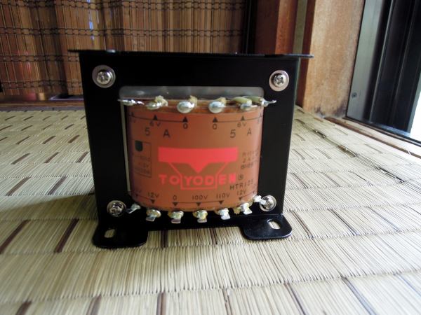 The 211 heater is 10 V / 3.25 A, and the power transformer with 2 windings for heater is as expensive
as the output transformer. So I decided to purchase a heater transformer. Heater transformer with
2 windings of 6 to 12 V / 5 A could be purchased for only 5,000 yen. This makes it possible to use
the power transformer that was previously used for 811A and 300B single amplifiers. Since there
is a capacity of 5 A, it became just fine when I made the primary 110 V terminal and the secondary
10 V terminal.
The 211 heater is 10 V / 3.25 A, and the power transformer with 2 windings for heater is as expensive
as the output transformer. So I decided to purchase a heater transformer. Heater transformer with
2 windings of 6 to 12 V / 5 A could be purchased for only 5,000 yen. This makes it possible to use
the power transformer that was previously used for 811A and 300B single amplifiers. Since there
is a capacity of 5 A, it became just fine when I made the primary 110 V terminal and the secondary
10 V terminal.
 I was satisfied with the sound of trans-driven 811A and 300B, so I will try the cathode choke drive
this time. As a result of various searches, I found an inexpensive choke coil called C3035 made by
SEL. The inductance is 30 H, the current capacity is 35 mA which is not so large, the cost performance
is the highest. They cost only about 3,000 yen.
I was satisfied with the sound of trans-driven 811A and 300B, so I will try the cathode choke drive
this time. As a result of various searches, I found an inexpensive choke coil called C3035 made by
SEL. The inductance is 30 H, the current capacity is 35 mA which is not so large, the cost performance
is the highest. They cost only about 3,000 yen.
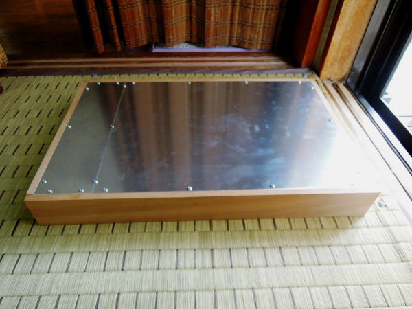 I have good skill to make chassis cheap. I bought two aluminum plates of 40 mm x 30 mm x thickness 2 mm and
30 mm x 20 mm x thickness 2 mm and cut out partly and made a 50 mm x 30 mm chassis. This size is the
limited size that can be accommodated in the stereo rack. After that, I bought wood board with a width of
60 mm and a thickness of 10 mm and fixed it with adhesive. The cost of the chassis was about 3,500 yen.
I have good skill to make chassis cheap. I bought two aluminum plates of 40 mm x 30 mm x thickness 2 mm and
30 mm x 20 mm x thickness 2 mm and cut out partly and made a 50 mm x 30 mm chassis. This size is the
limited size that can be accommodated in the stereo rack. After that, I bought wood board with a width of
60 mm and a thickness of 10 mm and fixed it with adhesive. The cost of the chassis was about 3,500 yen.
 I decided the circuit diagram after examining it on the net. Since transformer coupling was fully
satisfactory with 811A and 300B, I made it to cathode follower drive this time. Although the purity of
the sound of the cathode follower by mere resistance seems to be high, I chose the choke drive because
I like the unique sound in the tube amp. Initially the drive tube was 5687, but because of high gm its
motion was unstable with the current of 20 mA, and it became very hot, so it replaced it with triode
connection of 6CW5. Since 6CW5 is a plate loss less than half the rating, it does not become hot so
much, and cathode follower tube does not matter its quality, so even low quality will play a sufficient
role. Originally it is usual to run 211 at 1,000 V at about 55 mA, but at this time I decided to use 70
mA at 830 V and a load resistance of 5 kΩ. 211 is a direct heat triode but because of the transmission
tube the internal resistance is large and the damping factor is small so I installed the NFB switch so
that the overall negative feedback of 2 dB can be applied. In my poor ears I prefer the sound of No-NFB.
Residual noise is 0.5 mV even at No-NFB, and it is excellent for amplifier with heater voltage of 10 V.
I decided the circuit diagram after examining it on the net. Since transformer coupling was fully
satisfactory with 811A and 300B, I made it to cathode follower drive this time. Although the purity of
the sound of the cathode follower by mere resistance seems to be high, I chose the choke drive because
I like the unique sound in the tube amp. Initially the drive tube was 5687, but because of high gm its
motion was unstable with the current of 20 mA, and it became very hot, so it replaced it with triode
connection of 6CW5. Since 6CW5 is a plate loss less than half the rating, it does not become hot so
much, and cathode follower tube does not matter its quality, so even low quality will play a sufficient
role. Originally it is usual to run 211 at 1,000 V at about 55 mA, but at this time I decided to use 70
mA at 830 V and a load resistance of 5 kΩ. 211 is a direct heat triode but because of the transmission
tube the internal resistance is large and the damping factor is small so I installed the NFB switch so
that the overall negative feedback of 2 dB can be applied. In my poor ears I prefer the sound of No-NFB.
Residual noise is 0.5 mV even at No-NFB, and it is excellent for amplifier with heater voltage of 10 V.
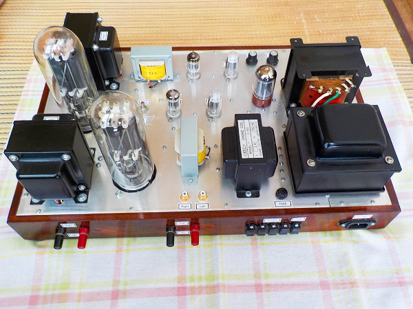
 I will upload completed amplifier. Drilling of an aluminum plate with a thickness of 2 mm was
quite hard. That's why it took me nearly a month to complete the amplifier, so I did not feel
like shooting pictures etc. on the way. As you can see there is no symmetry at all. The position
and direction of parts are inconsistent. Actually, since the electromagnetic induction hum from
the power transformer enters the output transformer, it eventually became such an unnatural
disposition. The output transformer was separated from the power transformer as much as possible,
so that induced hum was minimized.
I will upload completed amplifier. Drilling of an aluminum plate with a thickness of 2 mm was
quite hard. That's why it took me nearly a month to complete the amplifier, so I did not feel
like shooting pictures etc. on the way. As you can see there is no symmetry at all. The position
and direction of parts are inconsistent. Actually, since the electromagnetic induction hum from
the power transformer enters the output transformer, it eventually became such an unnatural
disposition. The output transformer was separated from the power transformer as much as possible,
so that induced hum was minimized.
 It is the back of amplifier. Total weight is about 20 kg, it is very heavy. Because the space
at the upper part of the vacuum tube is narrow and there is a problem with cooling, I send wind
by electric fan from the back of the stereo rack. The power supply of the compact fan of AC100V
is linked to the power switch of the amplifier from the outlet of the back of the amplifier.
In addition, since this machine becomes a main amplifier, I have the AC outlet terminal for
distributing power supply to other amplifier and tuner etc.
It is the back of amplifier. Total weight is about 20 kg, it is very heavy. Because the space
at the upper part of the vacuum tube is narrow and there is a problem with cooling, I send wind
by electric fan from the back of the stereo rack. The power supply of the compact fan of AC100V
is linked to the power switch of the amplifier from the outlet of the back of the amplifier.
In addition, since this machine becomes a main amplifier, I have the AC outlet terminal for
distributing power supply to other amplifier and tuner etc.
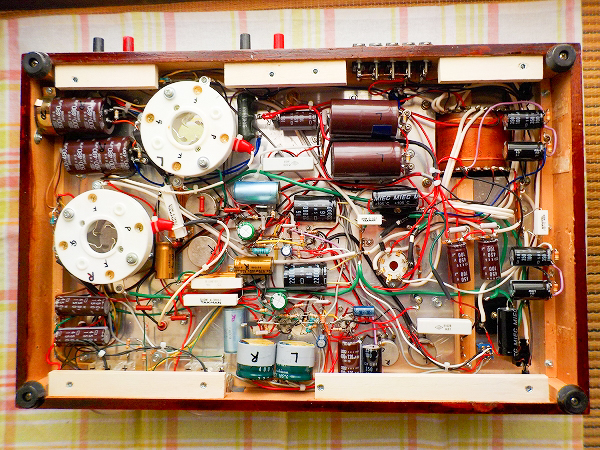
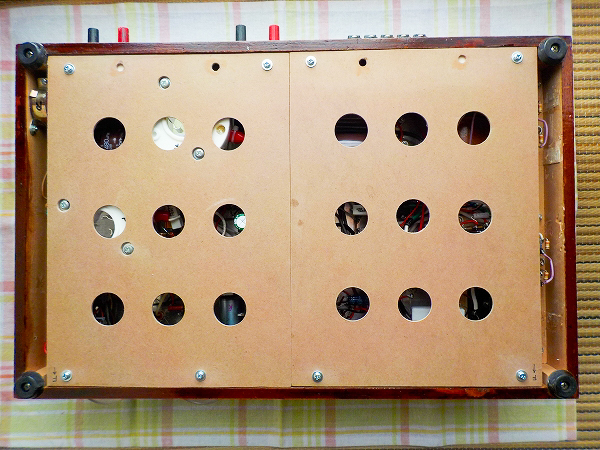 It is the photograph of inside the chassis. Dirty wiring is seen as usual. Although the maximum
voltage is about 900 V, special high voltage electric wires are not used, and wires are wired so
that electric wires float in the air as much as possible. So rubber gloves can not be released
during adjustment work.
It is the photograph of inside the chassis. Dirty wiring is seen as usual. Although the maximum
voltage is about 900 V, special high voltage electric wires are not used, and wires are wired so
that electric wires float in the air as much as possible. So rubber gloves can not be released
during adjustment work.
 I installed it at the bottom of the stereo rack, but the height is not enough, so I usually send
wind from behind with a fan. It is fun to watch the heater lit brightly, but it is too hot in the
summer.
I installed it at the bottom of the stereo rack, but the height is not enough, so I usually send
wind from behind with a fan. It is fun to watch the heater lit brightly, but it is too hot in the
summer.
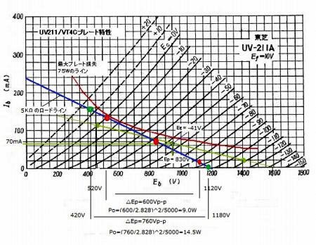 I calculated the maximum output when 211 was operated with Ep = 830 V, Ip = 70 mA, Eg = -41 V,
load resistance 5 kΩ. I borrowed plate characteristics from the Internet and drew a load line
with a load resistance of 5 kΩ. In the class A operation with the grid voltage in the negative
range, the calculated maximum output is 9.0 W. Also, in the A2 operation which swings to the
positive region where the grid current flows, the maximum output is 14.5 W, which is consistent
with the measurement result of the following input/output characteristics. If the load resistance
is increased, the load line will fall asleep, so the plate voltage that can be used will be wider
and the maximum output will be increased, but it will rather be reduced by the A1 class operation
of small output. The meaning of adopting the cathode choke follower disappears, but in my case who
usually enjoy music with small volume, there is no problem with the load resistance of 5 kΩ at all.
I calculated the maximum output when 211 was operated with Ep = 830 V, Ip = 70 mA, Eg = -41 V,
load resistance 5 kΩ. I borrowed plate characteristics from the Internet and drew a load line
with a load resistance of 5 kΩ. In the class A operation with the grid voltage in the negative
range, the calculated maximum output is 9.0 W. Also, in the A2 operation which swings to the
positive region where the grid current flows, the maximum output is 14.5 W, which is consistent
with the measurement result of the following input/output characteristics. If the load resistance
is increased, the load line will fall asleep, so the plate voltage that can be used will be wider
and the maximum output will be increased, but it will rather be reduced by the A1 class operation
of small output. The meaning of adopting the cathode choke follower disappears, but in my case who
usually enjoy music with small volume, there is no problem with the load resistance of 5 kΩ at all.
 It is the input / output characteristic of R channel at 1 kHz frequency. Voltage gain at No-NFB is
about 20 times, and the output is linear up to about 10 W, but the waveform will collapse from around
10 W or more. If I ignore the distortion, the maximum output will be about 15W. Calculating the
amplifier gain roughly, it becomes 10 × 8 = 80 times in 2 steps 12AU7A, 0.9 times in the cathode
follower of 6CW5, 7 times in 211, 1/25 times in the output transformer, 20 times in total. In the
small audio room, the power of about 2 to 3 W is enough, so it is usually used in class A1 operation.
When applying an overall negative feedback of about 2 dB, the voltage gain becomes 16 times but the
maximum output is the same. The damping factor is 1.0 for no feedback and only 1.5 for negative
feedback, which is very small. I think that the damping factor will increase if the amount of
negative feedback is further increased, but I don’t like the sound with large amount of negative
feedback.
It is the input / output characteristic of R channel at 1 kHz frequency. Voltage gain at No-NFB is
about 20 times, and the output is linear up to about 10 W, but the waveform will collapse from around
10 W or more. If I ignore the distortion, the maximum output will be about 15W. Calculating the
amplifier gain roughly, it becomes 10 × 8 = 80 times in 2 steps 12AU7A, 0.9 times in the cathode
follower of 6CW5, 7 times in 211, 1/25 times in the output transformer, 20 times in total. In the
small audio room, the power of about 2 to 3 W is enough, so it is usually used in class A1 operation.
When applying an overall negative feedback of about 2 dB, the voltage gain becomes 16 times but the
maximum output is the same. The damping factor is 1.0 for no feedback and only 1.5 for negative
feedback, which is very small. I think that the damping factor will increase if the amount of
negative feedback is further increased, but I don’t like the sound with large amount of negative
feedback.
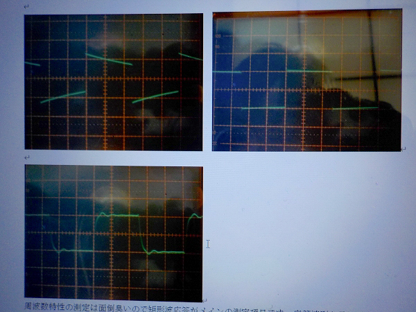
 Accurate measurement of electrical characteristics is troublesome, so rectangular wave response is
mainly done. As expected, at 100 Hz without feedback, small sag has occurred due to the sadness of
single amplifier, but there is no feeling of lack of bass.
Accurate measurement of electrical characteristics is troublesome, so rectangular wave response is
mainly done. As expected, at 100 Hz without feedback, small sag has occurred due to the sadness of
single amplifier, but there is no feeling of lack of bass.
 The waveform of 1 kHz without feedback is fairly normal. In case of bad output transformer, ringing will
clearly appear at 1 kHz but this amplifier has no problem.
The waveform of 1 kHz without feedback is fairly normal. In case of bad output transformer, ringing will
clearly appear at 1 kHz but this amplifier has no problem.
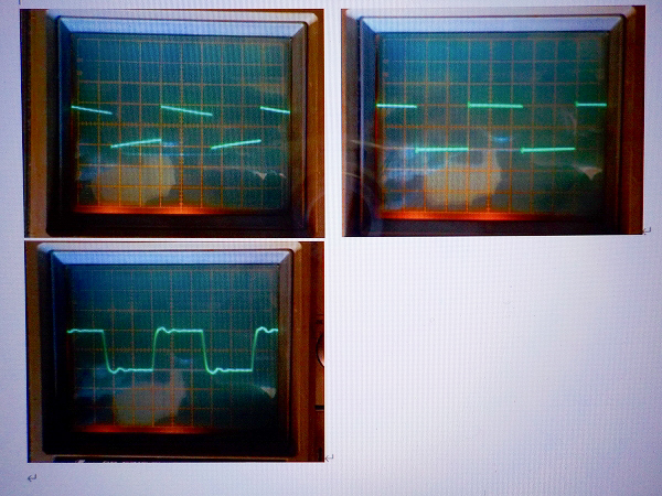 At 10 kHz without feedback, the rise of the waveform is dull and ringing can be seen. Initially I suspected
the cheap cathode choke, but when I observed the grid of the output tube 211 it was beautiful square wave.
This means that the criminal turned out to be the output transformer. Because it is the output transformer
with about 20,000 yen for 2 pieces, I think that ringing of this degree is normal. As a precaution, I changed
the wiring on the secondary side to change the pseudo load resistance from the current 5 kΩ to 6.7 kΩ,
10 kΩ, and tested whether the maximum output and ringing change. Instead of increasing the maximum output
somewhat the rise of the waveform worsened and the ringing became large. Finally 5 kΩ was judged to be
the best. If 8 Ω load is connected to an arbitrary terminal on the secondary side, the calculated primary
impedance changes between 1.25 kΩ and 10 kΩ, but I think that it is better for the output transformer to
demonstrate its full capabilities by using regular usage.
At 10 kHz without feedback, the rise of the waveform is dull and ringing can be seen. Initially I suspected
the cheap cathode choke, but when I observed the grid of the output tube 211 it was beautiful square wave.
This means that the criminal turned out to be the output transformer. Because it is the output transformer
with about 20,000 yen for 2 pieces, I think that ringing of this degree is normal. As a precaution, I changed
the wiring on the secondary side to change the pseudo load resistance from the current 5 kΩ to 6.7 kΩ,
10 kΩ, and tested whether the maximum output and ringing change. Instead of increasing the maximum output
somewhat the rise of the waveform worsened and the ringing became large. Finally 5 kΩ was judged to be
the best. If 8 Ω load is connected to an arbitrary terminal on the secondary side, the calculated primary
impedance changes between 1.25 kΩ and 10 kΩ, but I think that it is better for the output transformer to
demonstrate its full capabilities by using regular usage.